I am building boards using blank vero board, pins & copper wire, one finished the other 1/2 done, these will be great for experimentation but are a labour of love to build. Have to test & match some components now. As you can see I'm not rushing but should have one working cct in a few days.
The number of versions bouncing around here is enough to make a potential builder giddy but initially I'm interested to two versions only and I thought I would see what the experts think about how they compare theoretically. They differ only in VAS. 1) irf9610 2) casoded bd140s
Earlier in the thread a BJT VAS was discarded due to lack of OLG ( about 75dB ) but if a cascode is added the gain increases to almost 100dB which is flat to about 1Khz which with my CLG target of 20 - 24 dB should be plenty of FB.
Many here have stated that they prefer a BJT for VAS and I think the cascode makes it a viable contender.
In simulation I saw advantages in keeping the VAS current high so I'm begining with 20mA. I would be interested in alernative device suggestions.
My new PC scope arrived today which is great but I can tell you that building when all your usual parts, tools & testing gear are on a boat on the Atlantic is quite a challenge !
Try a Jfet Bjt cfp as input transistor and (or) for vas use the mosfet but as a follower followed by a bjt vas, like in the beta enhanced vas of D Self. You could also use bjt vas in grounded base after the mosfet follower which is my prefered choice.
Mikelm,
After listening all morning to the bjt (bc560) vas I can say that I find the bjt has a more clinical sound (not that I have tried cascoding it as you are). I am almost glad to have this outcome as it is consistent with what I thought of the bd140 vas with jfet input a few weeks back.
That said, I think the zvp3310a takes the cake and gives you musicality with detail and precision. It's my choice....if you can get it stable.
Going to try something new tomorrow...
It looks like just miller compensation to me, except a damping resistor thrown in to decrease the Q of the connection to avoid creating new resonances. - keantoken
exactly !
.my guess is you will prefer the 9610.
You might be right Greg, but a cascoded BJT in a VAS is a very different animal from a solo one - no miller capacitance amplification - therefore an easier load & better response and much higher OLG. From 75db to almost 100dB, that's 17 times more feedback with the cascode in my cct than with a solo - with the corresponding increase in PSNRR.
We're not just talking about the qualities of a individual component - it's much more a complex mix of how a component interacts with a design. If we change the interaction, the self same component that sounded bad could really shine.
I'm not saying that 9610 won't sound better but another one of my obsessions is debunking the "mythology" around some "beliefs" in audio - the classic one being "valves sound better" as if there is something mystical going on inside a valve that we will never really understand and therefore it should be revered - whereas in reality if we understand the parameters that govern how valves work and how they interact inside valve amps we can come a long way to attaining the same kind of sound . . . if we want to.
here endeth another rant - hehe
")
just sorted 110 Jfets ! . . . . another step completed
over & out
mike
Last edited:
Circuit comments
Oh - that look's very tasty SWF!
I would look at the gate stopper VAS resistor of 221 ohms though...
It will limit the open loop bandwidth of the VAS.
Better to apply cap(s) on R4 (2n2?) for a pole or R14 for extension. R14 of 50 Ohms might be a bit high as well? Should be able to go down to about 20 Ohms?
A little Source degeneration of the input Fet perhaps? just 10 Ohms or so?
Should help at bit with the DC and 1st stage linearity issues...
ohh and Output filter? 47n with 10ohms/2w (min) should do the trick...
All the 'best of wind' - marvellous effort going in here
DocO
Hugh,
Thanks again, how's this one? Found an example in the examples folder of lt spice!
Not entirely sure what this is actually doing. Might be a good topic next time we speak on the phone!
P.S. don't pay too much attention to the actual schematic. I'm just trying to get the stability testing sorted. The vas is actually at 10mA.
Oh - that look's very tasty SWF!
I would look at the gate stopper VAS resistor of 221 ohms though...
It will limit the open loop bandwidth of the VAS.
Better to apply cap(s) on R4 (2n2?) for a pole or R14 for extension. R14 of 50 Ohms might be a bit high as well? Should be able to go down to about 20 Ohms?
A little Source degeneration of the input Fet perhaps? just 10 Ohms or so?
Should help at bit with the DC and 1st stage linearity issues...
ohh and Output filter? 47n with 10ohms/2w (min) should do the trick...
All the 'best of wind' - marvellous effort going in here
DocO
Last edited:
SWF, you might try the file loopgain2.asc in the examples folder of LTSpice. It is more accurate than the first file. See here:
http://www.diyaudio.com/forums/software-tools/101810-spice-simulation-21.html#post2476869
I have a default "simulator directive rig" that I use for every amplifier I simulate. It integrates most of what I need into several command switches and signal sources. I recommend you do the same if you want to make simulation more accurate without being exhausting.
Also, maybe you should avoid wirewound, and use carbon composition for the output snubber? Carbon comps have no extra inductance unlike film and wirewound resistors.
- keantoken
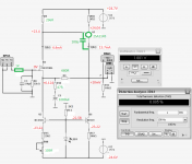
Result with lineup rec version
I have done some more experiment with lineup's recommended version with BJT VAS:
Pic 1 - the Green is the value that I used, Red is the actual reading,
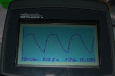
Pic 2 - bOth rise time & fall time were poor.
I have done some more experiment with lineup's recommended version with BJT VAS:
Pic 1 - the Green is the value that I used, Red is the actual reading,
Pic 2 - bOth rise time & fall time were poor.
Attachments
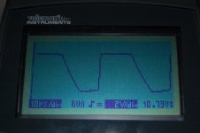
Test result with lineup's ultimate version + Wahab's TMC
I have done some more experiment with lineup's ultimate version + Wahab's TMC mod:
Pic 1 - the Green is the value that I used, Red is the actual reading,
Pic 2 - rise time improved a lot & fall time was still poor.
The input square wave was 12kHz, the addition of Q4 (2SK117GR) improved the rise time a lot. I did not notice any difference with the TMC & darlington VAS.
I will build SWF's BJT version.
Attachments
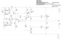
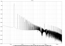
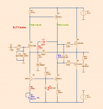
Here is BJT VAS with TMC.
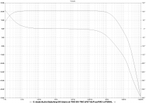
Distortion from 0.022 at 1kHz down to 0.02 at 100kHz.
Attached:
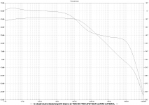
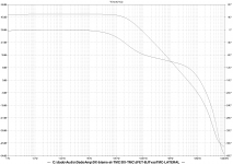
OLG, CLG, FFT, schematic and LTspice zip file
dado
Distortion from 0.022 at 1kHz down to 0.02 at 100kHz.
Attached:
OLG, CLG, FFT, schematic and LTspice zip file
dado
Attachments
-
 JFET-BJTvasTMC-LATERAL-sch.png88.7 KB · Views: 509
 -
 JFET-BJTvasTMC-LATERAL-OLG.png152.9 KB · Views: 319
 -
 JFET-BJTvasTMC-LATERAL-CLG.png151.9 KB · Views: 147
 -
 JFET-BJTvasTMC-LATERAL-FFT-1kHz.png125.7 KB · Views: 160
 -
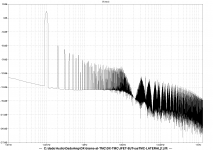
 JFET-BJTvasTMC-LATERAL-FFT-20kHz.png165.4 KB · Views: 154
 -
 JFET-BJTvasTMC-LATERAL-FFT-100kHz.png167.9 KB · Views: 143
 -
JFET-BJTvasTMC-LATERAL.zip9.5 KB · Views: 65
I may as well post my SPICE file.
All models not included come from here:
CordellAudio.com - SPICE Models
- keantoken
All models not included come from here:
CordellAudio.com - SPICE Models
- keantoken
Attachments
sng001
I do not think the open loop gain is large enough to use TMC.
If open loop gain is low than it makes no difference
Do not say "I do not think the open loop gain is large enough to use TMC", simulate it.
Here is OLG for the same schematic I used before with 20pF of Miller cap only, no TMC.
dado.
Attachments
Typical Fetzilla is by design low open loop gain.
TMC is probably better used in other amplifiers. Other designs.
If I am wrong about that circuit, then good. Go ahead use TMC.
Use TMC where it makes a difference to lower THD.
Note: Not necessarily the same as Better Sound
Use TMC not because it is fancy be able to say: 'I use TMC'.
TMC is probably better used in other amplifiers. Other designs.
If I am wrong about that circuit, then good. Go ahead use TMC.
Use TMC where it makes a difference to lower THD.
Note: Not necessarily the same as Better Sound
Use TMC not because it is fancy be able to say: 'I use TMC'.
BJT Fetzilla with 2N5401, 2N551
Here is a take on BJT Fetzilla.
As the current demand is only like 5 mA, we can use small signal TO-92 bipolar.
Here I use 2N5401/5551.
But can also be BC550C/560C or 2SA970/SC2240 or 2N3904/3906.
Circuit below simulates well. THD is acceptably low.
Here is a take on BJT Fetzilla.
As the current demand is only like 5 mA, we can use small signal TO-92 bipolar.
Here I use 2N5401/5551.
But can also be BC550C/560C or 2SA970/SC2240 or 2N3904/3906.
Circuit below simulates well. THD is acceptably low.
Attachments
- Status
- This old topic is closed. If you want to reopen this topic, contact a moderator using the "Report Post" button.
- Home
- Amplifiers
- Solid State
- JFET input, MOSFET VAS, LATERAL output = Perfect!!