I did not know that Torrent licenses software. Exactly how does that work ?
I think he meant to link to NI Multisim - National Instruments

Hi all,
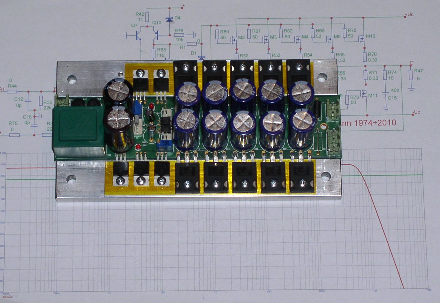
I have ordered 10 each of the ECX10N20R and ECX10P20R lateral mosfets to have a go at one of these amplifiers.
However, I'm still trying to find a suitable and readily available input jfet. Currently I'm leaning towards the J309, but the circuit does not sim particularly well with this device and I think this is in part due to the large source resistor that this device requires to keep the current of the input stage within reasonable limits which, as an unwanted consequence, reduces the gain of the input stage. The other reason is the slightly lower transconductance of this device over that proposed by lineup in his schematic.
Any thoughts on an alternative? I was thinking that it might be possible to use a ccs with the input stage but this might create its own problems. Thoughts?
Appreciate your advice!
Greg.
Hugh,
Thanks for your reply.
I would like to avoid the 2sk170 if at all possible as it is a difficult to find part. I would prefer to use something that can be ordered from digikey, farnell, mouser or RS, or even direct from a manufacturer (Fairchild have ordering direct on their website).
Which input filter cap are you referring to? I was going to build lineup's design with the single jfet input which as far as I can tell doesn't have a filter cap?
Thanks again,
Greg.
Great work. Because the lateral MOSFET in complementary version is die out more and more, the actually challange for the future is to find a topology with only N-Channel MOSFETs (resp. only NPN BjT), but at least the same results.
Follow threads are in this case of interest:
http://www.diyaudio.com/forums/soli...e-ended-related-solid-state-output-stage.html
http://www.diyaudio.com/forums/soli...better-audio-non-complements-audio-power.html
http://www.diyaudio.com/forums/soli...-models-quasi-complementary-power-output.html
http://www.diyaudio.com/forums/solid-state/154388-its-cheap-its-n-its-dirty-its-circlomos-4.html
Last edited:
Well, it uses IRF710 and was drawn aiming for high voltage into 1k load.
But sure, similar with IRFP240 would be possible for load 8 Ohm/4Ohm.
About quasi N-Channel having better sound, I do not think so.
It is my standpoint, that in order to influence sound
any amplifier must have so much distortion that it changes the input signal.
A well designed amplifier has no influence.
It is true to the input signal.
It is no way impossible to get distortion below hearing limit. Not only in opamps.
One good amplifier makes no sound.
I'd be happy to know an amplifier design, that has no annoying audible influence. For full range applications an CSPP topology is for me here the best choice and for only midrange/high frequency the so called "Single ended" output - read carefully this article:Well, it uses IRF710 and was drawn aiming for high voltage into 1k load.
But sure, similar with IRFP240 would be possible for load 8 Ohm/4Ohm.
About quasi N-Channel having better sound, I do not think so.
It is my standpoint, that in order to influence sound
any amplifier must have so much distortion that it changes the input signal.
A well designed amplifier has no influence.
It is true to the input signal.
It is no way impossible to get distortion below hearing limit. Not only in opamps.
One good amplifier makes no sound.
http://www.passlabs.com/pdfs/articles/seclassa.pdf
If you compare an amp with topology from post #1 against a "ZEN" (in easiest version) in a midrange/high frequency speaker system most listeners would prefer the last despite the fact, that the measuring THD results much more bad than that one of the circuit from post #1.
Last edited:
Performance is essentially unchanged, around 0.00095% at +20dBU (13W into 8R @ 1KHz) which is close enough for government work.
The weak point is the extreme tetchiness of output offset control. It depends hugely on the pinpoint accuracy of the current source which supplies Q1, the JFET. This would be best solved with a servo, I suspect.
Thanks to Michael for an excellent design.
Cheers,
Hugh
View attachment 220855
That fet amp must have another weak point, it may not better than BJT version of Quad 303. And I don't know what C4 doing there? I feel that they (half CFA plus bootstrap) has similar minor result with another old low DF approach.
All,
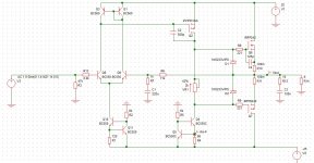
I know this is getting away from lineup's original plan, but this is where I am heading with this design should a decent jfet not present itself. BC transistors are super cheap and plentiful unlike 2SK170.
I don't have models for the laterals so I had to use IRFP240/9240. The actual amp will use the laterals I mentioned above, and run about 1A of bias. I had to use a fairly large miller cap to prevent HF oscillations.
What do you think?
Attachments
I would prefer to use something that can be ordered from digikey, farnell, mouser or RS
2SK937.pdf $0.67 at RS.
Regards
James
tiefbassGreat work. Because the lateral MOSFET in complementary version is die out more and more, the actually challange for the future is to find a topology with only N-Channel MOSFETs (resp. only NPN BjT), but at least the same results.
I have been inspired to do some N-Channel simulations.
I think it is easier when working in Class A like Nelson Pass mostly does.
Of course it is no coincedence that people love Pass amps.
I start one thread.
SPICE Models for your laterals.All,
I know this is getting away from lineup's original plan, but this is where I am heading with this design should a decent jfet not present itself. BC transistors are super cheap and plentiful unlike 2SK170.
I don't have models for the laterals so I had to use IRFP240/9240. The actual amp will use the laterals I mentioned above, and run about 1A of bias. I had to use a fairly large miller cap to prevent HF oscillations.
What do you think?
.SUBCKT ECX10N20 1 2 3
* Node 1 -> Drain
* Node 2 -> Gate
* Node 3 -> Source
M1 9 7 8 8 MM L=1 W=1
.MODEL MM NMOS LEVEL=1 IS=1e-32
+VTO=0.473 LAMBDA=0.092 KP=1.585
RS 8 3 0.41
D1 8 9 MD
.MODEL MD D IS=1.0e-32 N=50 BV=250
+CJO=1.0e-9 VJ=0.7 M=0.5
RDS 8 9 1e+06
RD 9 1 0.58
RG 2 7 80
CAP1 7 8 400e-12
CAP 7 4 10.5e-12
D2 4 9 MDD
.MODEL MDD D IS=1e-32 N=50
+CJO=94.8e-12 VJ=0.3 M=1
.ENDS ECX10N20
.SUBCKT ECX10P20 1 2 3
* Node 1 -> Drain
* Node 2 -> Gate
* Node 3 -> Source
M1 9 7 8 8 MM L=1 W=1
.MODEL MM PMOS LEVEL=1 IS=1e-32
+VTO=-0.426 LAMBDA=0.073 KP=0.673
RS 8 3 0.342
D1 9 8 MD
.MODEL MD D IS=1.0e-32 N=50 BV=250
+CJO=1.45e-9 VJ=0.446 M=0.377
RDS 8 9 1e+06
RD 9 1 0.523
RG 2 7 45.2
CAP1 7 8 696e-12
CAP 7 4 15.2e-12
D2 9 4 MDD
.MODEL MDD D IS=1e-32 N=50
+CJO=27.6e-12 VJ=0.817 M=0.871
.ENDS ECX10P20
The circuit will work just as well.All,
I know this is getting away from lineup's original plan, but this is where I am heading with this design should a decent jfet not present itself. BC transistors are super cheap and plentiful unlike 2SK170.
I am happy you soon will have a very own amplifier.
The laterals you have are real great devices.
BC550C and BC560C are fine transistors. Low noise and high gain.
The MOSFET vas. I would have liked you had one ZVN3310A at bottom.
But the BC550 will work.
The nice thing is is only one potentiometer to set the bias of the laterals.
I think you get away with only 5mA current for the VAS.
Dont forget to add a RC filter at input.I had to use a fairly large miller cap to prevent HF oscillations.
I use one 1k resistor in series with input
and after that resistor a 220p capacitor to ground.
Code:
--1k--
      |
     220p
|- Status
- This old topic is closed. If you want to reopen this topic, contact a moderator using the "Report Post" button.
- Home
- Amplifiers
- Solid State
- JFET input, MOSFET VAS, LATERAL output = Perfect!!