I don't get the Fetzilla with 2SK30A to Work, and yes there are some error in the Layout but i think i sorted most of it out on the Build.
Maybe it is something with the IRF9610 Pinout because there is none in the International Rectifier Sheet, only in the Vishay one.
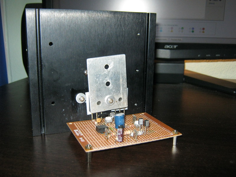
The next one go,s on a Stripgrid Bord, i hate those breadboard,s wear the Dot,s come of so easy.
Maybe it is something with the IRF9610 Pinout because there is none in the International Rectifier Sheet, only in the Vishay one.

The next one go,s on a Stripgrid Bord, i hate those breadboard,s wear the Dot,s come of so easy.
Last edited:
Yay! My lateral mosfets have arrived. Still waiting on the jfets though
Thank you lineup, this is more in line with what I thought (in fact I got 6mA), but I didn't want to question your experience. In any case the current is easily increased by altering R14/15 as you said.
5-6mA is more than enough for laterals I think, remembering that there is a dedicated 5-6mA low impedance drive for each lateral.
I still don't understand the weird gate waveform of the bottom FET that I posted earlier though.
Yes, I think jfets and mosfets have definite advantages for the input and output stages, however the VAS may be better with a BJT - depending on the circuit.
The main thing that defines the circuit is that it is a simple 3 stage amplifier with a direct coupled single ended input and a VAS directly driving the output (though this is not so true for quasi version). Also it is defined by nice distortion character which is the result of the SE input.
I think how we get to the end result does not matter as long as this basic configuration is kept. We don't know what works yet. No circuit has been built but will be soon. Circuits have been posted here that are easily tried. The quasi circuit especially is easy and can be made with cheap signal transistors and vertical fets that many will have already from their attempts at pass style circuits. You are encouraged to have a go. Some might prefer the VAS with a CCS for lower distortion, so might prefer the bootstrap circuit for a bit more warmth. Also, as Hugh mentioned, you might prefer the quasi version for the same reason.
Excuse me friends.
In swordfishy Quasi circuit Q1 and Q2 runs at 5 mA (4V/750 Ohm)
This is better than 2mA, but I would like to make it 10mA.
We can change R14/R15 to 470 Ohm.
This makes more current pass the need of the Gate.
This is for HEXFETs like IRFP240/IRFP9240
Thank you lineup, this is more in line with what I thought (in fact I got 6mA), but I didn't want to question your experience. In any case the current is easily increased by altering R14/15 as you said.
5-6mA is more than enough for laterals I think, remembering that there is a dedicated 5-6mA low impedance drive for each lateral.
I still don't understand the weird gate waveform of the bottom FET that I posted earlier though.
But this topic is more about using JFET input and MOSFETs
Yes, I think jfets and mosfets have definite advantages for the input and output stages, however the VAS may be better with a BJT - depending on the circuit.
The main thing that defines the circuit is that it is a simple 3 stage amplifier with a direct coupled single ended input and a VAS directly driving the output (though this is not so true for quasi version). Also it is defined by nice distortion character which is the result of the SE input.
I think how we get to the end result does not matter as long as this basic configuration is kept. We don't know what works yet. No circuit has been built but will be soon. Circuits have been posted here that are easily tried. The quasi circuit especially is easy and can be made with cheap signal transistors and vertical fets that many will have already from their attempts at pass style circuits. You are encouraged to have a go. Some might prefer the VAS with a CCS for lower distortion, so might prefer the bootstrap circuit for a bit more warmth. Also, as Hugh mentioned, you might prefer the quasi version for the same reason.
I'm with you....Years of building, listening, and observing the audiophile taste have shown me pretty clearly that people talk dry but drink sweet....
People like a bit of warmth to the music, that's why tube amps are so popular. It doesn't have to be much, either, around 0.02% H2 makes all the difference....
Last edited:
I don't get the Fetzilla with 2SK30A to Work
Danspy,
Well done for being the first to build something. I'm sorry it's not working.
The vishay and irf pinouts will be the same.
Now, first things first.
1) How much current through your input fet? (What is the size of your drain resistor and how much voltage is across it?)
2) How much current though your VAS? (What is the value of your bias resistance and bootstrap resistors and the voltage across each of them?)
3) What is the current through your output fet source resistors. (What resistors did you use and what voltage is across them?)
4) What is your DC offset?
5) Are any devices getting hot?
6) Which schematic are you using exactly?
Let us know these things and we'll go from there.
Greg.
Last edited:
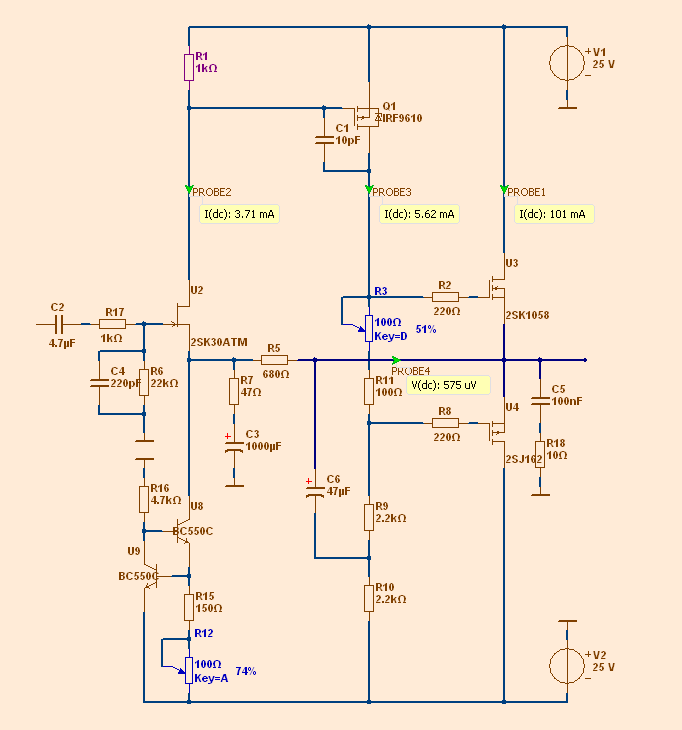
1k and 1,5Volt1) How much current through your input fet? (What is the size of your drain resistor and how much voltage is across it?)
2,7/2,7 on +-28Volt Supply = 5mA2) How much current though your VAS? (What is the value of your bias resistance and bootstrap resistors and the voltage across each of them?)
3) What is the current through your output fet source resistors. (What resistors did you use and what voltage is across them?)
The source resistors are 0,1/1Watt Dale LVR ad i get 3,5mV true them at every Time, an no increase or decrease wen i turn the Pot.
-26,6VoltWhat is your DC offset?
No5) Are any devices getting hot?
http://www.diyaudio.com/forums/solid-state/186650-jfet-input-mosfet-vas-lateral-output-perfect-18.html#post25622326) Which schematic are you using exactly?
Lineup,
I like the look of that circuit with the bootstrap VAS!
If this circuit makes less than 1% distortion at 20kHz and 10W in real life I'll be very happy.
Have you noticed with these circuits when simming them that the distortion does not seem to change much between 1W and 20W? This is what I am finding and it is the first amplifier I have simulated and had such a result.
Something I like to do is sim the THD at 20kHz too, as this is when we really start to see the effect of the fet gate capacitance come in to play, and in fact sometime more current in the input and VAS stages may create more distortion at 1kHz but cause significant improvement at 20kHz. I wonder what will prove to be the best compromise?
How did you arrive at 47uF for the bootstrap capacitor? Did you try any other values?
Thanks again, I am enjoying seeing this progress.
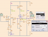
Circuit shows much lower than 1% at 10 Watt.
Yes, it does not increase THD much. It is a low curve.
Bootstrap 47uF.
2.2k//2.2k = 1.1k x 47uF = 51.7 uFk
This is like having 1uF for 47k in input.
47uF could be 100uF,
but 47uFk is enough to come to 3Hz for lower -3dB
Danspy,
The first thing is to check your layout very carefully, which I can't do, but we'll assume it is correct for now. BTW, can your jfet handle a 28v supply? Most are rated at 25v.
Then do this:
1) Set R3 to minimum value. This will prevent fets from turning on too much and blowing themselves up while you're adjusting. Also set R12 to maximum value. This will prevent destruction of input fet and VAS fet by keeping current of input stage low. Now turn it on.
2) Measure voltage on VAS inbetween R3 and R11. It needs to be close to 0 mv (only for now, we will change later).
If it is higher than 0mv you need to increase R12. This will decrease the current through R1, which will drop the voltage across it and turn on the VAS fet less, bringing the midpoint VAS voltage down.
If it is lower than 0mV you need to decrease R12 which will have the opposite effect. This is the situation you are most likely currently in.
If you run out of adjustment for R12, you may need to increase R1. However, currently you are only running 1.5mA, so I don't think this should be a problem. You want 3.5mA or so.
3) Now, move your voltmeter to the output and double check the DC offset at the output.
4) Put your voltmeter across one the the output source resistors. Now, depending on whether you want to run class AB (100mA bias) or class A (1A Bias), adjust R3 until you get 10mV across the source resistor for class AB or 100mV for class A.
5) Now, check your DC offset at the output. It will be off again due to the different Vgs of the mosfets. Adjust using R12 as described before to get it as close as possible to 0v.
6) Double check your current through R1. It should be no more than 4mA - (4v across it).
7) Double check your VAS current. It should be no more than 5-6mA or so max (11v across the bootstrap resistors).
8) Double check current through source resistors for output fets.
You should now have a working amplifier!
Hope this helps!
If you still have problems let us know.
Last edited:
Maybe it is something with the IRF9610 Pinout because there is none in the International Rectifier Sheet, only in the Vishay one.
IRF devices are GDS, Gate-Drain-Source
200mA! Wow, something is very wrong. How are you measuring this exactly? What voltage is across R1?
Ok, first things first. What is the voltage rating of the jfet and your rail voltage? It is possible you have exceeded its supply voltage and it is shorting out. I can't find a datasheet, but most audio jfets are 25v. I think you were using 28v rails so this will be a problem.
If this is the case you will need to make the cascode version to keep the voltage at the drain to 14v.
Otherwise, maybe you have the wrong pinout for the CCS transistors and the CCS is not working properly.
Danspy,
R7 is connected to ground through a capacitor which means DC can not flow through it. No current should flow through R7 unless a signal is applied. So the are two main possibilities.
1) you have an error in your construction.
2) C3 is shorted due to reverse polarity or connection. You may need a bipolar capacitor here. You can use two back to back electrolytics as a substitute.
Maybe this is what miib was hinting at?
If I make a PCB I always try to divide my circuit in parts.
Input,voltage and current.
I always solder input first, if that's ok I solder the VAS stage and also my output pairs .
It's easier to find/solve/prevent a problem that way.
You can try to divide your circuit to find in what part of the circuit the problem is.
Hope this helps in future.
Input,voltage and current.
I always solder input first, if that's ok I solder the VAS stage and also my output pairs .
It's easier to find/solve/prevent a problem that way.
You can try to divide your circuit to find in what part of the circuit the problem is.
Hope this helps in future.

- Status
- This old topic is closed. If you want to reopen this topic, contact a moderator using the "Report Post" button.
- Home
- Amplifiers
- Solid State
- JFET input, MOSFET VAS, LATERAL output = Perfect!!