Hi
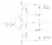
I was more in the thinking this way...biased Class AB with app 600 mA through the laterals
The design is also scalable by inserting a cascodes like the ones used in the One Jfet-amplifer....
To be honest i think I like the single-ended design of that One-Jfet-Amplifier concept better.. distortion is app the same, but bear in mind we are dealing with simulations where things are more ideal than in the real world...
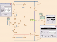
Distortion is rather low and with a very nice distribution...
Harmonic Frequency Fourier Normalized Phase Normalized
Number [Hz] Component Component [degree] Phase [deg]
1 1.000e+03 1.814e+00 1.000e+00 -0.40° 0.00°
2 2.000e+03 6.368e-05 3.510e-05 84.68° 85.09°
3 3.000e+03 1.066e-06 5.873e-07 34.34° 34.75°
4 4.000e+03 9.654e-09 5.321e-09 -88.21° -87.81°
5 5.000e+03 4.155e-10 2.290e-10 -122.44° -122.04°
6 6.000e+03 1.670e-10 9.204e-11 122.01° 122.42°
7 7.000e+03 7.513e-11 4.141e-11 -108.82° -108.41°
8 8.000e+03 1.438e-10 7.923e-11 -83.59° -83.19°
9 9.000e+03 3.134e-11 1.727e-11 -132.79° -132.39°
Total Harmonic Distortion: 0.003510%
I was more in the thinking this way...biased Class AB with app 600 mA through the laterals
The design is also scalable by inserting a cascodes like the ones used in the One Jfet-amplifer....
To be honest i think I like the single-ended design of that One-Jfet-Amplifier concept better.. distortion is app the same, but bear in mind we are dealing with simulations where things are more ideal than in the real world...
Distortion is rather low and with a very nice distribution...
Harmonic Frequency Fourier Normalized Phase Normalized
Number [Hz] Component Component [degree] Phase [deg]
1 1.000e+03 1.814e+00 1.000e+00 -0.40° 0.00°
2 2.000e+03 6.368e-05 3.510e-05 84.68° 85.09°
3 3.000e+03 1.066e-06 5.873e-07 34.34° 34.75°
4 4.000e+03 9.654e-09 5.321e-09 -88.21° -87.81°
5 5.000e+03 4.155e-10 2.290e-10 -122.44° -122.04°
6 6.000e+03 1.670e-10 9.204e-11 122.01° 122.42°
7 7.000e+03 7.513e-11 4.141e-11 -108.82° -108.41°
8 8.000e+03 1.438e-10 7.923e-11 -83.59° -83.19°
9 9.000e+03 3.134e-11 1.727e-11 -132.79° -132.39°
Total Harmonic Distortion: 0.003510%
Attachments
Last edited:
MultiSim 10.Lineup,
I like your biasing with the current mirrors. Interesting.
What software are you using?
"Electronic Workbench Multisim 10.0 Portable.rar Torrent Download"
It is fairly easy to install being portable.
Yes, the spectrum is nice. LIke I show in one post above.Hi
I was more in the thinking this way...biased Class AB with app 600 mA through the laterals
The design is also scalable by inserting a cascodes like the ones used in the One Jfet-amplifer....
To be honest i think I like the single-ended design of that One-Jfet-Amplifier concept better.. distortion is app the same, but bear in mind we are dealing with simulations where things are more ideal than in the real world...
Distortion is rather low and with a very nice distribution...
Most 2nd at any power output. And nicely falling harmonics.
Last edited:
3 transistors mirror added to my concept will lower dist, but the Fourier will not be as nice.Lineup.. have you tried to add those two extra transistors in my concept...wonder how that sims in your workbench..??
I think the mirror will take room from VGS.
Jfet_balanced as you posted, I have simmed. It has normal push-pull.
It is a very good amplifier.
With lower value current feedback resistors
it gets close to hifi numbers regarding THD.
Class AB with at least 200-250 mA bias made nice tests.
2SJ74 can only take 25 Volt VGDS
Last edited:
I have done numerous sim designs with CFA, Current feedback amp. And explored such amplifiers.Its a short, simple journey from where you are now Lineup to a current feedback amplifier.
Why don't you give it a try? ;-)
In fact I like CFA very much.
-----
Here is F5 by Pass, simplified.
It is very close to Zenotron.


Last edited:
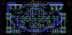
This is my final modification for Zenotron.
- Current sources for easy JFET loads
- 10/150 Ohm feedback resistors
The Fourier shows nice falling harmonics with 2nd at top at all levels.
Max 16 Watt Class A into 8 Ohm at less than 0.200% THD
Hmmm
It does not work or I made a mistake.
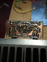
I dont have 2sk170/sj74, so its 2sk246/sj103.
Attachments
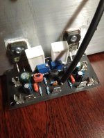
Looks like the mirror problem.
When I desolder these transistors and soldier two 1,2k on place of Q1/3, amplifier is working and i can regulate dc / current.
When soldering on mirrors, on output I have 2Vdc, and cant regulate it. 2sj162 gets 11mA, 2sk1058 nothing, through the mirror R4/5 (I changed it to 2x4.3k) flows 4.9mA, but on the potentiometers R15 0mA, R16 21mA?
I checked the transistors in the current mirror and they are good.
Last edited:
")
As Mirlo mentioned earlier, you need to add some 100R resistors to all the mirror emitters (4 of them). Mirrors with no degeneration work well only in ICs.
You can also use some CCSs - with LEDs as voltage references for example - mirrors don't make any difference here. Dynamic loads do.
You can also use some CCSs - with LEDs as voltage references for example - mirrors don't make any difference here. Dynamic loads do.
100ohm resistors to emitters, nothing changed that. I'm just letting it work that way, and I will not be having fun running, I will leave it that way.
I will desolder the transistors in the mirror, and listen. The time has come for Zenquito soldering, may it work.
I will desolder the transistors in the mirror, and listen. The time has come for Zenquito soldering, may it work.
Attachments
- Status
- This old topic is closed. If you want to reopen this topic, contact a moderator using the "Report Post" button.
- Home
- Amplifiers
- Solid State
- Zenotron. Minimalist FET power amplifier. Improvements?