Hi all,
This is a subject that has essentially never been discussed at DIYaudio.com, maybe for good reason, maybe just because it’s not widely known..
Here is a previous thread I have found:
http://www.diyaudio.com/forums/solid-state/73465-smala-amplifier-concept.html
There was one other I think but I can’t find it.
I have recently done some work on these amplifiers, spent about 10 weeks researching and simulating. No building though. I had some reasonable results with a self oscillating parallel composite amplifier, here are some rough figures:
-100W @ 89% efficiency up to around 10KHZ <0.1% THD
-100W @ 82% efficiency at 20KHZ <0.02% THD
Load = 8R//100nF
If there is enough interest with DIYers I will post my results and write up, it will require me finding a decent way to upload it first (3MB PDF).. i’ve got a crud load of Christmas shopping to do last minute beforehand!
Cheers
Craig
Attachments
Member
Joined 2009
Paid Member
Read this: http://quad405.com/jaes.pdf
and then note this: Devialet High End Audio integrated amplifier
This thread has my interest too.
and then note this: Devialet High End Audio integrated amplifier
This thread has my interest too.
Please, take a look in this video and notice how Quad 405 sounds
YouTube - Csöves single ended VS Quad405
regards,
Carlos
YouTube - Csöves single ended VS Quad405
regards,
Carlos
Your simulation show the digital self oscillating with 60 times higher frequency than linear (sine) signal. I am using less than 10 times higher frequency (says 100Khz) and still wishes lower than 100KHz to be used, because of sensing and controller limitation. Please built it and we may sharing in problems. You will need very fast equipment for your project, and it is hard job.
Similar but used for supply:
http://www.diyaudio.com/forums/soli...ere-diy-projects-post2223627.html#post2223627
Similar but used for supply:
http://www.diyaudio.com/forums/soli...ere-diy-projects-post2223627.html#post2223627
Last edited:
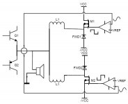
Bigun, yep exactly, the idea is very similar to the Quad 405 current dumping / error correcting principal, a few additional considerations are necessary for dealing with a switching dumper amplifier. Thanks for the interest.
Ontoaba, I think I allowed frequencies up to 500KHz without seeing masses of loss in SPICE.
Really the switching frequency is best kept lower, I agree. This is easily tweakable in my implementation.
I used IRFB4020 N-type FETS, so my results do depend on how good the model is. Driver was IXDD404, this was not a great choice but I was having issues getting driver SPICE models to work.
Cheers
Craig
Member
Joined 2009
Paid Member
The issue highlighted by vanderkooy was the time delay at the output of the ClassD power stage - resulting in a higher current draw from the ClassA stage. Do you see anything of concern in the simulations ? - or is your Class A stage simply beefy enough not to worry about it (I think this is what Vialet did, they used a beefy Class A stage).
Vanderkooy does mention this, he is correct, the delay in the control loop of the SMDS (switched mode dumping stage) is directly linked to the rise in correction current in the LCA (linear correction amplifier).
This is the phase lag he talks about and is a function of the hystersis thresholds, type of SMDS, bridging network and the active control loop component delay.
This can be controlled, the simplest method is by adjusting (lowering and shrinking) the hysteresis bands in the self oscillating controller (in my implementation anyway).
But in my sims the LCA was certainly beefy enough to cope, I didnt have time to work on a custom LCA so I used two good fast fairly powerful designs from the late (sadly) Professor Marshall Leach (Low TIM) and Giovani Stochino (Ultra fast power amp, thanks to Alex M's kindness).
Cheers
Craig
Member
Joined 2009
Paid Member
Member
Joined 2009
Paid Member
I didn't seriously expect to be able to hear anything properly via my computer speakers. But I did hear a difference, just don't know if it was real or my brain foolin' with me. I focussed on the first part i.e. Johnny Cash. To my ears, via an iMac, the tube sounds different from the Quad. I preferred the tube for Johnny Cash. When it switches to the Quad the high's don't sound right and the mids have lost something. The next track, Queen, sounds to me as if the bass is tighter on the Quad but I didn't like the sound as much. Weird, it can't be possible to really hear these differences via a microphone, youtube and an iMac, so I put it down to biassed expectations.
Hi, Bigun.
Lets stop comparing it with tubes first. This one is current based, that mean the output could be maintained to match with the load.
I know where the good sounds coming from, and this one may have it.
If I could generate 20KHz 80Vpeak with 100KHz and here 500KHz achieved, thats mean 100KHz 80Vpeak composite amplifier await. It is faster than conventional class AB.
I found only few from google results
Another SMALA:
http://www.itee.uq.edu.au/~aupec/aupec06/htdocs/content/pdf/160.pdf
http://innovexpo.itee.uq.edu.au/2003/exhibits/s354194/thesis.pdf
Realized SMALA, but looks bad:
http://innovexpo.itee.uq.edu.au/1998/thesis/wongcp/smala.pdf
Another reaalized SMALA, better than cheng peng has:
http://ddata.over-blog.com/xxxyyy/1/74/30/05/schemateque/AmpBassisteD.pdf
Member
Joined 2009
Paid Member
In general, I've learned to trust first impressions/gut feel in many situations and based on this I'll stick with my impression that the SE tube amp sounded better to my ears despite the playback quality.
That doesn't mean that a current dumping implementation as suggested in this thread can't sound very good - it may only mean that the implementation on the video wasn't as good as it could be.
That doesn't mean that a current dumping implementation as suggested in this thread can't sound very good - it may only mean that the implementation on the video wasn't as good as it could be.
I’ve read the two papers you posted there, both were really useful for me getting started, Geoffrey Walker has done some really good practical tests. I particularly liked his idea of having independent positive and negative rail tracking power converters, I used this topology in nearly all of my sims.
The dissertation links are new to me, although I agree that they don’t look as useful as the papers. My sources were mostly from IEEE database.
I did do some sims of the multi-level class power converter implementation, inspired by the first paper there. Although my results didn’t show much overall benefit using it. It does reduce the oscillation frequency a bit though.
What kind of implementation did you build ontoaba? can you post any details here?
I can’t upload 3MB at DIYaudio can I? Where do people generally upload large files in this forum?
Cheers
Craig
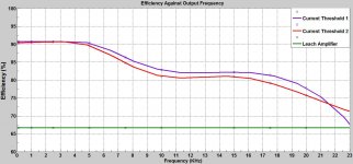
Too late to edit previous post, but here is a plot of efficiency of the system over output frequency. The two current thresholds are slightly different hysteresis bands. The size of the output coils was 200uH hence the efficiency rolloff significantly before 20KHz.
This is using the topology in post number 1 of this thread.
Fswitchmax for current threshold 2 is 423KHz (biggerhysteresis band)
Fswitchmax for current threshold 1 is 637KHz (smaller hysteresis band)
Cheers
Craig
This is using the topology in post number 1 of this thread.
Fswitchmax for current threshold 2 is 423KHz (biggerhysteresis band)
Fswitchmax for current threshold 1 is 637KHz (smaller hysteresis band)
Cheers
Craig
Attachments
Last edited:
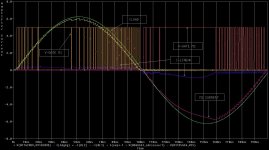
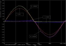
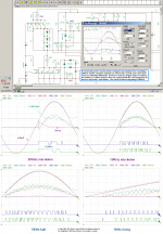
Hi, I am trying to simulate with tina 7.0 and my computer are too slow for this one. I only able to use emitter follower, added more complex makes it not showing up for long minutes. This (in my pictures) scope pictures takes very long time to capture, and there is differences each cycle, it may caused by its remaining current in inductors. I am still study it more.
I only able to use emitter follower, added more complex makes it not showing up for long minutes. This (in my pictures) scope pictures takes very long time to capture, and there is differences each cycle, it may caused by its remaining current in inductors. I am still study it more.Attachments
Last edited:
That efficiency results are dominated with linear and switching current output values. Linear current rises when the inductor in slow charging. With smaller inductors, it may have higher efficiency at high frequency.
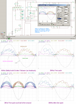
This picture, I am trying with topology at your first post for positive side and still using my current topology for negative side(still in EF without feedback), now only single switch, only little differences, it almost same.
Also I try opamp as error correction feedback, it faster (my simulator) with only single switch, and the ripple is reduced with feedback.
Your PDF, split it and zip them, or use another sites to upload your files.
Attachments
Last edited:
Hi Craig,
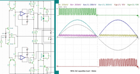
This is what I mean, a current based, and may have better sound among digitals.
I am planning to make it simplest in drivers and systems, but this thread getting onely?
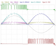
Operated at around 500KHz ; 0.1% THD at low power and 0.5% at high power.
About the efficiency, I don't know the best way to measure it, so please post your PDF, it may useful for me and for anyone here.
This is what I mean, a current based, and may have better sound among digitals.
I am planning to make it simplest in drivers and systems, but this thread getting onely?
Operated at around 500KHz ; 0.1% THD at low power and 0.5% at high power.
About the efficiency, I don't know the best way to measure it, so please post your PDF, it may useful for me and for anyone here.
Attachments
Last edited:
- Status
- This old topic is closed. If you want to reopen this topic, contact a moderator using the "Report Post" button.
- Home
- Amplifiers
- Solid State
- The Composite / Hybrid- Linear + Switching Power Amplifier