Something wrong with the transistors - no difference if they are connected or not.
You mean in the circuit you posted.
With no transistor in the circuit, the volume is the same?
You mean in the circuit you posted.
With no transistor in the circuit, the volume is the same?
Yes. I can't find the embarrassment smiliey again... hopefully I will have the last laugh.
Part of the reason is that I assumed the middle pin was the base, but that is not the case in all transistors.
The thousand steps to creating an amplifier circuit...
I could have followed the circuit exactly, which I did not. However the resources for learning electronics are not that great, at least from my point of view. So here is my note to self (and others)
1. Get a breadboard and some connecting wires.
2. Connect a 9V battery or a 1.5 volt battery to the bread board
(by the way, breadboards are not that straightforward to use : rows are all shorted out, except for the right side the sockets in the columns are all connected. Nothing on the breadboard to indicate it.
3. Connect a resistor to the circuit so as to obtain 300 mA
4. Connect an LED to the circuit (will it light with 300 mA? ) find out
5. Connect a transistor (emitter and collector, depending on if it is NPN or PNP) in series with the resister
Does the LED come on? If so, the transistor is broken/shorted out.
Next step: Use of the transistor as a switch
6. Connect a resistor and a power supply in series with the base and the collector (assume NPN transistor) so as to obtain the required base current required to turn on the transistor.
Does the transistor turn on when connected?
7. Connect a variable resistor in series with the second power supply circuit and slowly increase / decrease the variable resistor.
Does the LED gradually dim/get brighter? If so the circuit is working as an amplifier.
8. Connect the audio input in place of the second power supply, keeping the resistor in place.
Maybe too much available information. I have got much more useful, reliable information in this here forum than the previous sites I have seen. The Wikibooks on the subject are not complete. There are some free books that are good, not sure I can post them here.
I ran an LED off the 9V so I think I can sacrifice the LED for the moment. But thanks.
I ran an LED off the 9V so I think I can sacrifice the LED for the moment. But thanks.
I wondered how hard it was to get good electronics in your area.
"SCION Electronics - The Most Trusted Name in Electronics"
Transistors – Scion Electronics
2N2222 Transistor රු3.00 == 2 cents ($0.02)
2N3055 Transistor රු65.00 == $0.37
2N3904 Transistor රු4.00 == 2 cents
2N3906 Transistor රු1.50 == 1 cent
"SCION Electronics - The Most Trusted Name in Electronics"
Transistors – Scion Electronics
2N2222 Transistor රු3.00 == 2 cents ($0.02)
2N3055 Transistor රු65.00 == $0.37
2N3904 Transistor රු4.00 == 2 cents
2N3906 Transistor රු1.50 == 1 cent
The concept..
The point of it was to try out the experiment suggested "build amplifier from broken phone charger'. So I have removed two transistors from these to check if this is possible.
There is a place down the road which will sell me these transistors - in fact they even had a replacement for the BA5406 IC which cost less than a dollar. I will be purchasing a few of these today.
I wondered how hard it was to get good electronics in your area.
"SCION Electronics - The Most Trusted Name in Electronics"
...
2N3904 Transistor රු4.00 == 2 cents
2N3906 Transistor රු1.50 == 1 cent
The point of it was to try out the experiment suggested "build amplifier from broken phone charger'. So I have removed two transistors from these to check if this is possible.
There is a place down the road which will sell me these transistors - in fact they even had a replacement for the BA5406 IC which cost less than a dollar. I will be purchasing a few of these today.
300mA is a lot for LED. For a little one it is 10-20 ma. I recommend a 500 ohm limiting resistor. For a 9v battery this is also a lot
In my time there were only books. There are many resources available on the Internet")
So: that exercise has been a failure. In fact the latest circuit resulted in a soft, distorted form of the music, hardly audible, from the speaker.
I tested 300 mA in the circuit initially with an LED and a 10 Ohm resistor and the 300 mA does not pass through the collector emitter, so the transistor is not shorted. This is with the salvage 13001.
Next step will be to use the 13001 as a transistor operated switch with the LED.
Do you believe he is actually in Sri Lanka?...
Can't see why not. Sri Lanka's population is ten times the population of Maine USA, even bigger than Buenos Aires, so he is more probable than you or I. The economy is good; so are the schools. The excellent English could be from the centuries of English rule and cultural influence.
Right on! We were not a typical family as we spoke English at home. We value education, but education is in Sinhala for most of the population, the result of decision made many years ago.The excellent English could be from the centuries of English rule and cultural influence.
BTW my first degree is from USA: I lived and studied in New York in the 1980s. President Reagan was the President back then.
OK so back to the extremely frustrating project. I connected up the 13001 as a switch, powered by 9V on the main circuit and by a 1.5V battery through the base. I used the circuit shown here: (under "Cut Off Mode")
Working of Transistor as a Switch - NPN and PNP Transistors
An LED was hooked up in series with the Emitter, Collector, resistor and battery. When the 1.5 V battery was connected to the base, the LED lit up. I used a variable resistor as well to dim the LED by varying the base voltage. I took some measurements:
Input values : 0 to 0.5 mA
Output values: 13.2 to 16 mA (max) . 13.2 mA was measure by removing the 1.5 V and connecting those terminals to each other.
There is more than one scheme on your link. All are correct. Base current must be limited to permissible values for this type of transistor. For example, using a series-connected resistor. Direct insertion of a 1.5 battery can cause the transistor to malfunction.
A fresh 9v battery will provide up to 300mA current. Discharged - how much it will turn out
Transistors 13001 are high voltage with low current gain.
A fresh 9v battery will provide up to 300mA current. Discharged - how much it will turn out
Transistors 13001 are high voltage with low current gain.
Last edited:
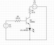
The Transistor as a switch
Here is the circuit in Circuit Lab ( CircuitLab - Editing "Unnamed Circuit" ). The 9 V battery was connected across the emitter and collector, with a resistor of 10 Ohms to reduce the current to the levels safe for the LED. The LED in this case anyway shows about 600K Ohm resistance so that explains the low current across the emitter and collector.
The 1.5V battery was connected to the base and the collector with a 470 Ohm resister to reduce the current again. In any case, the circuit worked, reducing the current in across the base caused the LED to glow less brightly.
I may have got the plus minus connections wrong, however the reason for the low currents is now apparent.
The next step will be to connect an audio input ( without a capacitor, I can use a 1kHZ tone to make sure the input frequency is reasonable, and keep the LED in the circuit, or maybe a light bulb, with a variable resistor in series for protection of the LED and check for variable brightness of the LED. If this works, I can work on getting the voltage swings on the output large enough to drive a speaker.
Attachments
There is more than one scheme on your link. All are correct. Base current must be limited to permissible values for this type of transistor. For example, using a series-connected resistor. Direct insertion of a 1.5 battery can cause the transistor to malfunction.
A fresh 9v battery will provide up to 300mA current. Discharged - how much it will turn out
Transistors 13001 are high voltage with low current gain.
Used a resistor to limit the current to the base. (see diagram). Using an input variable resistor should take care of this, what is output current from a laptop headphone out?
EDIT: shows 1.2 mA approx on music output. This music output is enough to drive a speaker to output music that is just barely audible. So this means that 1.2 mA will drive the speaker. 2 mA using the 1000 Hz tone from Online Tone Generator - Free, Simple and Easy to Use.
Given that the output was measured at 13.3 mA, this looks very promising.
Will have to check the 9V battery.
High voltage low current gain means this is not the best type of transistor for this application?
Last edited:
The diagram of the emitter follower is shown. The load is included in the emitter. The input voltage must exceed the operating voltage of the LED by 0.7V (Vbe).
Any (almost) general purpose transistor will do. For noticeable power (current), a transistor in a TO-126 or TO-220 package is needed.
Простейший усилитель звука на одном транзисторе за 15 минут
Any (almost) general purpose transistor will do. For noticeable power (current), a transistor in a TO-126 or TO-220 package is needed.
Простейший усилитель звука на одном транзисторе за 15 минут
Here is another circuit for a single transistor amplifier:
Simple Single Transistor Audio Amplifier Circuit
There is one difference between this and the switch circuit. The switch circuit is only concerned with positive currents and voltages from 0 to + maximum. The audio signal, however, has a minus component that this video mentions, so the entire input signal has to be boosted into the positive region in order to obtain amplification of the complete signal, both positive and negative. The function of the bias resistor achieves this, as I understand it.
I created this circuit in Falstad. Apparently it works as created.
$ 1 0.000005 16.13108636308289 60 15 53
w 240 48 336 48 0
r 240 48 240 208 0 110000
t 240 208 336 208 0 1 -5.602603183242531 0.621610495370204 100
w 240 352 336 352 0
g 240 352 240 384 0
R 240 48 144 48 0 0 40 9 0 0 0.5
r 336 48 336 192 0 4
r 336 224 336 352 0 1000
c 240 208 160 208 0 0.0000049999999999999996 3.8761219855710785
R 160 208 112 208 0 1 80 0.5 0 0 0.5
o 9 64 0 4098 0.625 0.00009765625 0 2 9 3
Circuit Simulator Applet
Working!!!
But a little distorted.
Using this circuit:
Simple Single Transistor Audio Amplifier Circuit
But a little distorted.
Using this circuit:
Simple Single Transistor Audio Amplifier Circuit
- Home
- Amplifiers
- Solid State
- Single gain stage transistor amplifier.