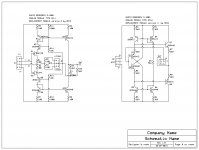
Okay, these are the changes I was proposing to make, for clarity purposes/removing potential ambiguity. Do all of these look correct? As I mentioned, I am not nearly as great as you are at determining the function and expected design of so many circuits yet, and I am hoping I did this correct. I circled any changes I made in red, to make them easy and quick to observe.
Attachments
Sure would have been nice to have this back in around 2010 when I had a D-100...
It made a nice space heater. I contacted the manufacturer and was told the AM's were no longer available and sold the D-100. Made the decision that I would never buy another amplifier made by the company, especially when the company tech I spoke with on the telephone suggested I buy their comparable model at the price of >$5000 after tax, title and license.
Instead, I moved onto my Marantz 1200, which I've probably got close to $10k worth of my time. But, I can work on the Marantz and have nothing better to do than work on the amp, learn audio electronics and caulk the bathtub, special things like that when working from home.
Do all of these look correct?
Yes.
@Taki525 I am unsure, but if they look the same, are labelled the same, and the physical layout (that you can view) is the same, I'd guess it's likely the same. With how concerned AR was about their own part numbers in many places (transistors and modules especially) I'd imagine they wouldn't use two identical part numbers that look the same, but are different.
@Nrik I appreciate it, I will test to make sure I didn't cook anything on my failed module board/s and try again, this time with less concern of trying to stuff everything back into the plastic shell of the module.
@Nrik I appreciate it, I will test to make sure I didn't cook anything on my failed module board/s and try again, this time with less concern of trying to stuff everything back into the plastic shell of the module.
@Nrik I appreciate it, I will test to make sure I didn't cook anything on my failed module board/s and try again, this time with less concern of trying to stuff everything back into the plastic shell of the module.
I made mine on veroboard.
I tried to find a picture, but no succes.
They still work, says the guy who has the amp now.
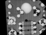
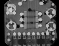
Well, I've gotten everything back together. The one card set I made, worked fine. The channel with the originals, has about -3.5v to -5v DC on the outputs, but still produces audio. I've found the blue wire that comes from pin 2 on AM2 and goes to the board below, to have the DC offset almost exactly, on it. Does this mean I have to replace that module too, I'm assuming? I'm certainly hoping not, but, you know. It seems to build up, from 0, to around -5v, from power up over the course of a few seconds. With both blue wires disconnected at the main board, I've found the good channel has around 10v there (on the AM2/main board side) and the bad one has around 17v there, ish. On the side going to the sub-boards for the transistors, I find around 25v (bad) and 17v (created/good). For clarification, these measurements are, electrically speaking, between R39/40, and the AM2 module pin 2, when opened there. This thing has been a nightmare, and as much as I'd love not to rebuild a second set of cards, if I have to I certainly will, just to get it finished.
Edit 1: Checked the pin 1 on AM2, seems to be about the same -4v to -5v area. I'm fearing more that I'll be rebuilding a second set of modules.
Edit 1: Checked the pin 1 on AM2, seems to be about the same -4v to -5v area. I'm fearing more that I'll be rebuilding a second set of modules.
Last edited:
Hi,
I'm in the middle of fixing a faulty D-52B and found this thread very useful as all the AM1 & AM2 modules have already gone bad.
There's one small point though: R10 in AM1 is likely 56k rather than 5.6k as I can literally measure it between OUT and GND pins.
Anyway thank you Nrik for your fantastic job.
Duong
hoangduongo: Wauw, that is the resistor which actually sets the internal gain.
I just did some calculations, and with 5k6 the internal gain before global feedback will be 41dB, and with 56K it rises to 61dB.
The global feedback ( outside the modules ) sets the gain at 25dB for the ARC D-100/D110, so it should not make any big difference, and both values would work.
But it can change the level of TIM distortion and the bandwith and thereby the risk of self-oscillation.
I did mention that I was in doubt of the compensation circuit (R10, R9+ cap), and of course one should always check for oscillation with a scope after a major repair with other components.
I believe that I actually also measured the 5k6 back in the days, so it is possible that Audio Research made different versions of the modules.
Thank you for the comment hoangduongo.

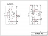
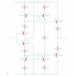
I have AM-1 working fine, but still can't get an AM-2 to work. Can anyone see an error in my Eagle schematic? +50 is the top rail, -50 is the bottom, Input on the left, Output on the right - this is all pretty much by inspection but I don't want to have any assumptions.
Attachments
Last edited:
An externally hosted image should be here but it was not working when we last tested it.
Need help from you guys.
For AM2, the PIN 2 of J2 (gnd), is it has no connection to the circuit?
I’m rebuilding these with designed PCB’s for drop in replacement over at AudioKarma thanks to this thread: Audio Research D-100A Restore | Audiokarma Home Audio Stereo Discussion Forums
Dear All, Seeking help and solution on my AM1. currently i have make some am 1 and am2 on pcb board. During the testing, my am1 resistors is getting very hot and some burn smell. I tried change a few resistors from 1watt to 2watts but the problem still the same. Anyone know that the resistors is using how many ohm type? Currently i using 100ohms. Please help.. thanks
Frank, your jumper on Q4/Q6 is wrong, needs to be base to emitter, not base to collectorI have AM-1 working fine, but still can't get an AM-2 to work. Can anyone see an error in my Eagle schematic? +50 is the top rail, -50 is the bottom, Input on the left, Output on the right - this is all pretty much by inspection but I don't want to have any assumptions.
- Home
- Amplifiers
- Solid State
- How to fix the Audio Research D-110 modules