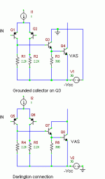
We could use two transistors for the VAS stage.
One is an emitter follower stage after the input stage feeding an ( ac) grounded emitter VAS transistor. The second would be a darlington VAS stage.
There is a difference in the distortion spectrum between the two . Is there any audible sonic difference between the two ? Any one prefered over the other ?
Attachments
Darlington introduces additional "Miller multiplied" Zcb distortion that is avoided in the 1st circuit with no countervailing advantage - no one would use Darlington for VAS
buffering the VAS input also enables larger distortion reduction from diff pair current mirror instead of the collector R shown
buffering the VAS input also enables larger distortion reduction from diff pair current mirror instead of the collector R shown
Thanks JCX . You've clarified again what the problems are .
However I asked about the audible differences because when I was trying out some schemes some time ago I 'expected' the buffered VAS to sound better but it was the reverse and I couldn't understand it. It just sounded cleaner. Strange ! Anyway never mind and thanks for taking time to reply.
However I asked about the audible differences because when I was trying out some schemes some time ago I 'expected' the buffered VAS to sound better but it was the reverse and I couldn't understand it. It just sounded cleaner. Strange ! Anyway never mind and thanks for taking time to reply.
Difference when clipping
The first circuit, when it clips, can supply nearly unlimited base current to the last transistor. That saturates the heck out of it...and it takes a long time to recover.
The second circuit, with the darlington, the collector voltage sags, limiting the base current, and the saturation of the darlington pair...as a result, it clips too, but comes out of clipping a bit sooner.
In the limit, the first circuit, when clipping to the negative rail, the input transistor can kill the transistor it drives...
Typically, the first circuit may need some kind of limiter of the drive current.
After reading this thread - I happened to notice on several commercial amplifier circuits (One was Sansui, don't recollect which one the other was) that they used the first style (collector on the first emitter follower to ground) with a moderately large (10K in one case) resistor in the collector circuit. My guess was originally to limit collector voltage, but realized it may be a form of current limiting for the transistors. (The circuit I saw had a 2.2 k resistor going from emitter to the supply rail and a 10k resistor with nothing attached to it going collector to ground. Second circuit used a 6.8k emitter resistor and a 10k resistor.
2.2K on the emitter sounds OK but 6.8K looks rather large ( very low Iq !). But then on ehas to look at the full circuit to determine proper operating currents. 10K on the collector will limit the current but I had used 1 K to minimise distortion in the emitter follower stage cause by a varying Vce.
Cheers.
Cheers.
- Status
- This old topic is closed. If you want to reopen this topic, contact a moderator using the "Report Post" button.
- Home
- Amplifiers
- Solid State
- Comparison of VAS using two transistors
