This amplifier sound quite flat and it is now under my modification.
I will post more info later.
http://i20.photobucket.com/albums/b206/etsang3/Krell/KST-100/krell_kst100.jpg
I will post more info later.
http://i20.photobucket.com/albums/b206/etsang3/Krell/KST-100/krell_kst100.jpg
An externally hosted image should be here but it was not working when we last tested it.

Hi Leon, for resistor, desoldering from the component side.
1. use a hook to hook one leg of the resistor
2. soldering iron to that leg and pull the leg up
3. Do this to another leg
4. Re-opened the holes with desoldering pump
For ecaps,
1. using 2 soldering iron together
2. Turn the PCB upside down
3. Add a bit of Tin to each soldering iron tip
4. Apply each soldering tip to each leg of the ecap for enough time (say 15 sec)
5. Pull the ecap only downward direction to extract it
6. Re-opened the holes with desoldering pump
O,K, but I don't think that you can improve there anything.More likely you will make it worser.The only thing what would be worth doing is converting this amp to class AB operation.Because now it's working in class A and consumes a lot of power.Why need you to heat up the air, you want listen music.
Over the course of its 10 year history, the KRELL name has become synonymous with audio products of uncompromising quality. The KST-100 Stereo Amplifier possesses a combination of classic KRELL attributes and new concepts that have evolved in recent years.
A new concept being incorporated in home audio equipment is balanced operation. Balanced systems have long been standard in professional applications. KRELL believes the sonic advantages are substantial and has included balanced circuitry in all products. Soundstage and dynamic presentation are dramatic and vivid, and overall noise is reduced. The KST-100 will accept both balanced and single-ended inputs.
The KST-100 is built to provide consistent performance for a lifetime. Superior build quality is a KRELL trademark. This is evident in the fit and finish of the external chassis, military-grade electronic components and proprietary structural parts. Internal construction is efficient and elegant. Virtually all hand wiring has been eliminated, resulting in a surprising improvement in sonic clarity. All gain and power supply stages operate in complete harmony with one another to insure uniform operation under the most diverse conditions.
The KST-100 is a Class A/B amplifier rated at 100 watts per channel into 8 ohms. Class A circuitry yields superior sonic quality because the active components operate in their most linear and predictable regions. The KST-100 input stages are full Class A. The output stages operate in Class A until approximately half power is reached, then gradually slide toward Class B operation. This allows the KST-100 to deliver ultimate sound quality at most listening levels while retaining tremendous reserve power for sharp attacks and transients.
The 100watt/8 ohm rating of the KST-100 is very conservative. Like all KRELL amplifiers, the KST-100 will drive extremely low impedance loads: it will deliver 800 watts continuously into 1 ohm!
All circuitry is direct-coupled from input to output, which is unique in the industry. There are no capacitors in the signal path to degrade the audio signal.
Rear panel connections provide for either a balanced input via an XLR connector or a single-ended input via an RCA connector. There are 2 sets of 5-way binding posts per channel to allow easy bi-wiring.
Additional value is gained from the KST-100's ability to be reprogrammed for mono operation by the owner. With the change of an existing amplifier to mono and the purchase of a second, dual-mono operation can be achieved without the inevitable loss from trading or selling used gear.
Dear Mr. Leon08,
First of all, thank you for your suggestion to me not to touch it. However, I must do the job at least to repair it.
Do you have this KST-100 amplifier or listened to it once ?
It is totally not the type of Krell amplifier you explained at the rest of you message. I have met a KRELL amplifier which was performing very close to what you have described (or have transferred the contents form the Krell amplifier brochure). Here is the one I have come across.
http://i20.photobucket.com/albums/b206/etsang3/KRELL_100/inside.jpg
http://i20.photobucket.com/albums/b206/etsang3/KRELL_100/wireschecking.jpg
I can cook eggs on top of it while enjoying the music.
With the warm surface of KST-100 (you will agree if you have touch one), I can put my hands on top as long as I like. It just does not has enough CONTENT inside to enable it to burn my hands. Check this out.
http://i20.photobucket.com/albums/b206/etsang3/Krell/KST-100/filtercaps.jpg
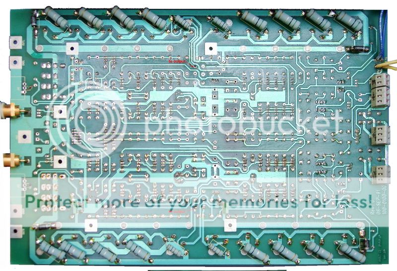
While the former KRELL I showed using all the wires with the size of a pencil. KST-100 is just using thin copper foil of PCB as the powering cables.
If my estimation is correct (from the heat of it), it's output circuit is just working at Class AB grade with ~ 10-20W in Class A. I will measure the BIAS current and tell you later.
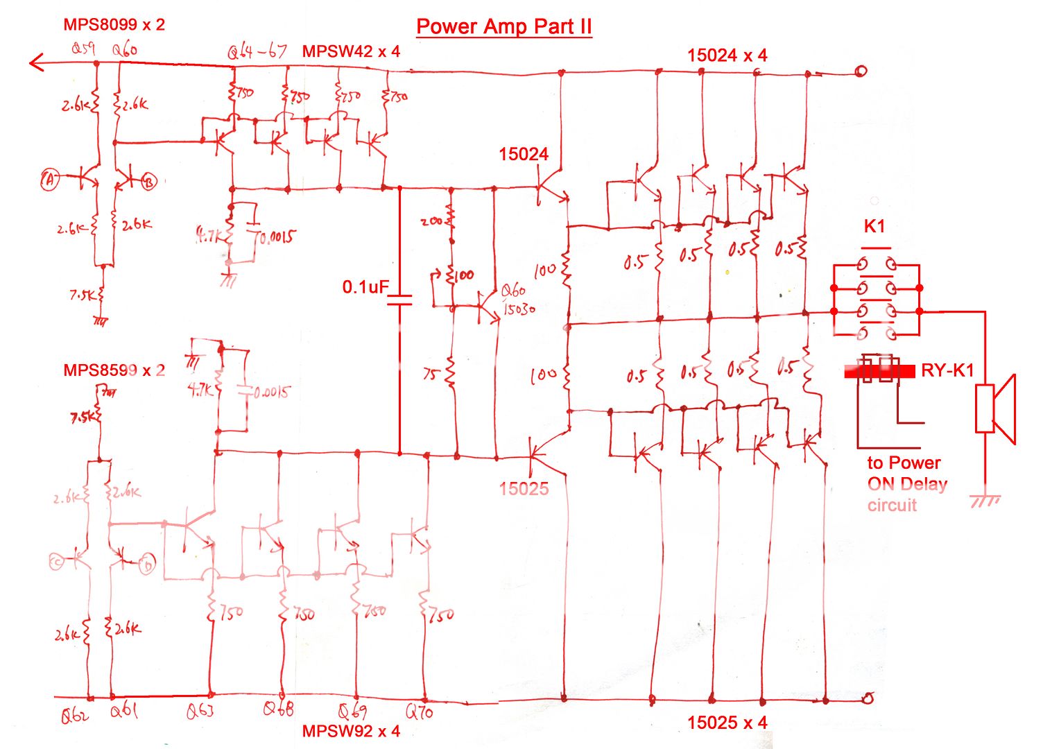
Unfortunately, even with this "Superior build quality trademark", I found a mistake at the PCB track that one leg of the 0.1uF film cap (BIAS bypass cap) is floating in the air ! I think I can do an IMPROVEMENT here with a good jumper wire. I will post the photo here later to let all the KST-100 owners to do this improvement too.
Have a nice day.
First of all, thank you for your suggestion to me not to touch it. However, I must do the job at least to repair it.
Do you have this KST-100 amplifier or listened to it once ?
It is totally not the type of Krell amplifier you explained at the rest of you message. I have met a KRELL amplifier which was performing very close to what you have described (or have transferred the contents form the Krell amplifier brochure). Here is the one I have come across.
http://i20.photobucket.com/albums/b206/etsang3/KRELL_100/inside.jpg
http://i20.photobucket.com/albums/b206/etsang3/KRELL_100/wireschecking.jpg
I can cook eggs on top of it while enjoying the music.
With the warm surface of KST-100 (you will agree if you have touch one), I can put my hands on top as long as I like. It just does not has enough CONTENT inside to enable it to burn my hands. Check this out.
http://i20.photobucket.com/albums/b206/etsang3/Krell/KST-100/filtercaps.jpg
While the former KRELL I showed using all the wires with the size of a pencil. KST-100 is just using thin copper foil of PCB as the powering cables.
If my estimation is correct (from the heat of it), it's output circuit is just working at Class AB grade with ~ 10-20W in Class A. I will measure the BIAS current and tell you later.
Unfortunately, even with this "Superior build quality trademark", I found a mistake at the PCB track that one leg of the 0.1uF film cap (BIAS bypass cap) is floating in the air ! I think I can do an IMPROVEMENT here with a good jumper wire. I will post the photo here later to let all the KST-100 owners to do this improvement too.
Have a nice day.
If this cap is already off then you can replace it with 1uF cap, don't know how much this will be an improvment, but some people recomend even 10uF here.This is not a bypass cap.This cap is needed for correct operation.Maybe it sounds bad because it's off?
I don't have a krell amplifier, but I know that class A is not efficient and produce a lot of heat.It has nothing with the size of filter caps or wiring.As described, the output stages operate in Class A until approximately half power is reached, then gradually slide toward Class B operation. Half power is 50 Watts.So this is as if you have a 50 Watt class A amp.I don't know how loud you used to listen your music, but 50 Watt must be pretty much loud, so usually you need only 10 or 20 watt at home.So if you decrease the bias for the output stage, say to 20 watts in class A you will half the current wich is going throu the transistors and as result the heat, wich it produces will also be halved and it will sound exactly as before.
I don't have a krell amplifier, but I know that class A is not efficient and produce a lot of heat.It has nothing with the size of filter caps or wiring.As described, the output stages operate in Class A until approximately half power is reached, then gradually slide toward Class B operation. Half power is 50 Watts.So this is as if you have a 50 Watt class A amp.I don't know how loud you used to listen your music, but 50 Watt must be pretty much loud, so usually you need only 10 or 20 watt at home.So if you decrease the bias for the output stage, say to 20 watts in class A you will half the current wich is going throu the transistors and as result the heat, wich it produces will also be halved and it will sound exactly as before.
Last edited:

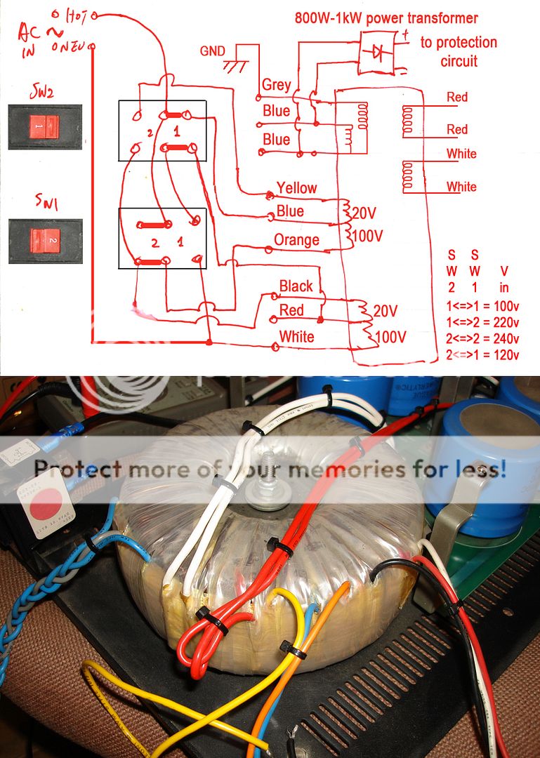
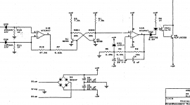
Since it is supplied by the Blue-Grey(CT)-Blue winding of the transformer after the rectifier and supply to the op-amp directly. +Vp=+12V and -Vp=-12V reference to Ground
Mains_input.jpg - Google Drive
Mains_input.jpg - Google Drive
Last edited:
Since it is supplied by the Blue-Grey(CT)-Blue winding of the transformer after the rectifier and supply to the op-amp directly. +Vp=+12V and -Vp=-12V reference to Ground
Mains_input.jpg - Google Drive
Many thanks Etsang3, I was thinking it was more about +/-15v or +/-18v DC. So i will check with +/-12v DC.
About bias, I read somewhere to adjust it at 100mA and elsewhere at 75mA... do you know what is the best sounding bias adjustment ?
- Home
- Amplifiers
- Solid State
- Krell KST-100 Amplifier