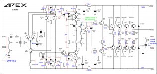
SR250
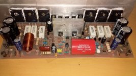
to sir mile thank you for this amp. it was tested the result was at first i cannot adjust bias so i replaced resistor in BD139 (B-C) 1K with 1K5. now i have set some bias but DC offset was high at about +/-55mV tested @55VDC
i think the bass was very reach, mid and high are just enough not that loud compared to my "SR200" or "AX14(3pairs)". with the following measurements attached. i hope for some advices...
these measurements was taken with shorted input but with 8r100w at output without resistor or bulb in series...
regards
sam
Attachments
This circuit isn't a soft start circuit!
It is just a push on push off circuit and uses main voltage for 4011 i. c. Use switch button suitable for main voltage only!!!
These are <<alwayes live circuits>>.

yes it's not i notice it when i redraw that circuit based on available components, but i continued since i have most of parts from salvaged units and the IC was available on local stores not expensive, used it for 300VA traffo
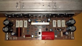
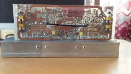
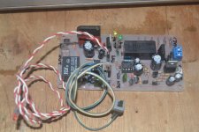
not a soft start thanks for reminding pls see the attached picture of completed work.
Attachments
Hi ! In order to get low DC offset, you should match 2N5551 input pair, with the same HFE.
to sir mile thank you for this amp. it was tested the result was at first i cannot adjust bias so i replaced resistor in BD139 (B-C) 1K with 1K5. now i have set some bias but DC offset was high at about +/-55mV tested @55VDC
i think the bass was very reach, mid and high are just enough not that loud compared to my "SR200" or "AX14(3pairs)". with the following measurements attached. i hope for some advices...
these measurements was taken with shorted input but with 8r100w at output without resistor or bulb in series...
regards
sam
Question of protection APEX SR150
I did not understand how the protection is connected, where to connect the AC-AC terminals, that go to the diodes 1N4007 ?
GIF , pdf and sprint-file:
I did not understand how the protection is connected, where to connect the AC-AC terminals, that go to the diodes 1N4007 ?
Hi Mr apex,
My sr200 amp was working nearly 3 year, the sound is excellent.
But yesterday, when I touch 1 side of heatsink was overheat, it's too hot, so i've unplug the power.
Please help me what's happened and how to solve it.
Thanks and regards,
Thanh Tran
If it's still playing okay then I would check the bias value.
I did not understand how the protection is connected, where to connect the AC-AC terminals, that go to the diodes 1N4007 ?
AC-AC goes to secondary of main transformer. when there is no secondary voltage, capacitor that comes after two 1n4007 diodes drains fast acting as "fast turn off loudspeaker". 2W resistors in series with relay coil must be calculated depending on relay coil resistance and voltage of transformer secondary. relay must have its defined voltage(better 24Vdc) and on that 2W resistor must be rest of voltage.
it takes a bit of calculating and real life measurements but 8n reality it works. so,you should make some calculations (current through relay related to voltage after capacitor wich is after 1n4007 diodes),ant to have a bit more capacitors of close enough capacity (+/-30% of capacity in schematic) and also a batch of 2W close enough to calculation value resistors. immediately it looks like a long stretch, but when you do he math and practice, and when it works as it should (you have a right voltage at relay contacts),it works all the way around, all the time! for a few years now...
use ohm-meter and connect it to a relay powering contacts. i have learned that resistor in series with diode, connected paralel with relay reuces time to shut down relay,and in that way saving relay contacts. ESP33 Loudspeaker Protection and Muting
"Figure 2A shows an alternative method you can use to damp the back-EMF from the relay, but to implement it properly, access to an oscilloscope is helpful (if not essential). If the resistors have approximately the same resistance as the relay coils, the back-EMF should (!) be limited to about the normal relay voltage, give or take 50% or so. In the tests I carried out (see Tests, below) using a 24V relay, the back-EMF was limited to about -30V, which would be fine in most cases.
This method is slightly cheaper than using zeners, but is less predictable. An additional alternative is to use a catch diode to the -ve power supply. A 1N4004 between the top of the relay string and the -ve amp supply will limit the back-EMF to the voltage of the -ve supply, so for the example case this would be -40V. I expect that this would be quite acceptable, but have not tried it. Make sure that the diode is connected the right way around - the cathode goes to the top of the relays, and the anode to the negative supply."
44250,sorry but any diode or diode-zener combination connected parallel to the relay coil doesn't protect the coil but the driver transistor.use ohm-meter and connect it to a relay powering contacts. i have learned that resistor in series with diode, connected paralel with relay reuces time to shut down relay,and in that way saving relay contacts. ESP33 Loudspeaker Protection and Muting
"Figure 2A shows an alternative method you can use to damp the back-EMF from the relay, but to implement it properly, access to an oscilloscope is helpful (if not essential). If the resistors have approximately the same resistance as the relay coils, the back-EMF should (!) be limited to about the normal relay voltage, give or take 50% or so. In the tests I carried out (see Tests, below) using a 24V relay, the back-EMF was limited to about -30V, which would be fine in most cases.
This method is slightly cheaper than using zeners, but is less predictable. An additional alternative is to use a catch diode to the -ve power supply. A 1N4004 between the top of the relay string and the -ve amp supply will limit the back-EMF to the voltage of the -ve supply, so for the example case this would be -40V. I expect that this would be quite acceptable, but have not tried it. Make sure that the diode is connected the right way around - the cathode goes to the top of the relays, and the anode to the negative supply."
Last edited:
it is true,but there is one more point - to reduce back-EMF and not to slow down relay opening its contacts. relay is being opened fastest when there is no zener diode or diode+resistor, and slowest when it has ordinary diode (without resistor in series with it) in parallel. this is "middle solution" or a compromise to save transistor from back-EMF and to save fast enough relay de-activation. there is a link at ESP33 page that directs to that theme.
Last edited:
SR250
yes of course... in pdf
Sir can u give layout of this plz sr250
yes of course... in pdf
Yes, use this schematic.
Regards
wich 2sk2145 to use,with suffix BL, Y or GR?
- Home
- Amplifiers
- Solid State
- Studio Reference Amplifier