Bob can you shed some light on how did you calculate/predict the driver and the output stage current.
For example, how can you tell the output stage current is 100mA and the drive current is 20mA?
And what were are have to take into consideration when picking the R11 and R12 values?
For example, how can you tell the output stage current is 100mA and the drive current is 20mA?
And what were are have to take into consideration when picking the R11 and R12 values?
Attachments
By inspection, you can see that the voltage between the bases of Q8 and Q9 is about 3Vbe*. That sets the voltage across the emitter resistors of the drivers, thus setting the driver current.
The voltage across the driver emitter resistors sets the voltage across the output stage emitter resistors, thus setting the bias current.
Jan
*There's 0.6V across R7, thus about 2Vbe across R8 because R8 ~ 2 x R7, total about 3Vbe.
The voltage across the driver emitter resistors sets the voltage across the output stage emitter resistors, thus setting the bias current.
Jan
*There's 0.6V across R7, thus about 2Vbe across R8 because R8 ~ 2 x R7, total about 3Vbe.
Last edited:
The SR needed has nothing much to do with the range of hearing or the FR range of a CD. Once upon a time maybe it did. Today is a different story.
Today, the digital processes are such that the DAC output has its noise and distortion shifted above 20Khz. However, most amplifiers have BW much greater than 20KHz. The unwanted "stuff" above 20KHz gets amplified as well.
If this stuff isnt amplified with low distortion, you get issues down in the audio range.
Typical "stuff" looks like this. The level is quite high out of the DAC/CD player. Examples from real gear (one is from a Mastering machine) -->


The PA slew rate needs to be much higher if it is to handle this "stuff" as well as < 20KHz music with low distortion. An amplifier tested by itself will look good with the 20KHz LP filter used for such tests but may not sound as good as it looks when in the music system.
The Mastering recorder/play deliberately left a post LP filter off as it could not be made good enough to not introduce its own audible affects. But, a LP on the PA input is a possible solution for a low SR amp. Mark Levinson PA have done this since forever and it contributes greatly to its success. IMO. It shouldnt affect noise too much but may have similar sonic signature of its own as the LP has to start removing close to 20KHz, also. Other solutions are the inherently high SR Current-Modem amp designs or a high SR VMA and no LP filters needed.
However, this HF Stuff amplified 30db by PA or so is going into the tweeter with some affect on its performance.
Your welcome.")
I think I will just listen to 24/96+ instead of CD. I have not bought a CD in years. Last month I gave away almost 1000 CD's I had. Just not listening to them any more....
THx-RNMarsh
Today, the digital processes are such that the DAC output has its noise and distortion shifted above 20Khz. However, most amplifiers have BW much greater than 20KHz. The unwanted "stuff" above 20KHz gets amplified as well.
If this stuff isnt amplified with low distortion, you get issues down in the audio range.
Typical "stuff" looks like this. The level is quite high out of the DAC/CD player. Examples from real gear (one is from a Mastering machine) -->
The PA slew rate needs to be much higher if it is to handle this "stuff" as well as < 20KHz music with low distortion. An amplifier tested by itself will look good with the 20KHz LP filter used for such tests but may not sound as good as it looks when in the music system.
The Mastering recorder/play deliberately left a post LP filter off as it could not be made good enough to not introduce its own audible affects. But, a LP on the PA input is a possible solution for a low SR amp. Mark Levinson PA have done this since forever and it contributes greatly to its success. IMO. It shouldnt affect noise too much but may have similar sonic signature of its own as the LP has to start removing close to 20KHz, also. Other solutions are the inherently high SR Current-Modem amp designs or a high SR VMA and no LP filters needed.
However, this HF Stuff amplified 30db by PA or so is going into the tweeter with some affect on its performance.
Your welcome.
I think I will just listen to 24/96+ instead of CD. I have not bought a CD in years. Last month I gave away almost 1000 CD's I had. Just not listening to them any more....
THx-RNMarsh
Last edited:
Well in this case:By inspection, you can see that the voltage between the bases of Q8 and Q9 is about 3Vbe*. That sets the voltage across the emitter resistors of the drivers, thus setting the driver current.
Vbe = 0.6V We will have the driver stage current range of the only I = (2.1V - 1.2V)/66Ω ≈ 13mA.
But at the same time, we see that V_R11 ≈ Vbe_Q10, therefore, the driver stage current I ≈ 18mA...21mA.
we see that V_R11 ≈ Vbe_Q10,
I don't think that is the case. What about V(R13)?
Jan
Raw DAC output has steps in it, which is why you require a LPF afterwards (aka reconstruction filter) - omitting such is poor engineering (the mastering argument is pretty specious I think, if you are converting to analog, you need a reconstruction filter - yes you might want to be able use a custom one I suppose, but these days with lots of oversampling its not hard to make a well behaved reconstruction filter)
Hi Mark,
I agree completely. It is incredibly irresponsible to make a non-oversampling DAC without the reconstruction filter. That seems to be the method these nos systems follow. They are missing the entire reason the industry went to oversampling to begin with.
-Chris
I agree completely. It is incredibly irresponsible to make a non-oversampling DAC without the reconstruction filter. That seems to be the method these nos systems follow. They are missing the entire reason the industry went to oversampling to begin with.
-Chris
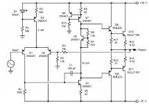
...how did you calculate/predict the driver and the output stage current.......have to take into consideration when picking the R11 and R12 values?
Output stage current is *trimmed* with R7 R8 to some "happy" value. "100mA" is a reasonable value for hFE fall-off of large transistors. It also "matches" hIE of transistor to the 0.33r emitter resistor which is a simple optimization for crossover action. (hFE is 30r at 1mA so 0.3r at 100mA.) (If your book says 26 Ohms, it is right; but at 25 deg C which is cool for a power amp; also there's some dead resistance; also it is pessimistic to round-up.)
0.33r is choosen because it is "small" compared to load (low loss) but can be "significant" compared to hIE. You find values from 0.1r to 1.0r in different designs.
We can NOT predict this current, except VERY roughly, by inspection or design. It depends too much on the various Vbes which are not tightly controlled. We trim the bias spreader with R7 R8.
The "Vas" stage current is defined by Vbe(Q6) against the 62r R9, about 10mA. The output stage base current in Q8 Q9 is small (0.1mA) and semi-cancelling (opposite directions). There is no other way out of here. So Q4 "must" idle at the same 10mA, and can swing to zero and 20mA if needed (we hope not so much swing). This allows for +/-10mA into the output stage which with typical low-end hFEs allows +/-10 Amps peak outputs. 8 and 4 Ohm loads need 4 and 8 Amps peak so this "works well". On paper it does not run out of current before it runs out of voltage.
A really "high end" amp would want more margin, Vas current well in excess of output stage current. But this tutorial plan only has four stages of current gain. We could scale-up all currents but then the input impedance gets too low. At this point the designer throws transistor(s) at the problem. A Darlington at Q4 has been popular. But running Vas at high current needs a large Q4 which may be a slower device, and this is the main gain of the whole amp. Other designers favor making Q8 Q9 Q10 Q11 a Triple, though this adds another Vbe to losses -or- using a Sziklai with potential stability issues.
R11 and R12 are picked with a dart-board. If very high (>1k) then when the transistor is supposed to turn "off" it takes a long time to drain the stored charge in the base region and you have a crossover glitch and overheating at high power and high frequency. If too small (<10r) the drivers work too hard. Values like 100r are popular. 33r, ~~20mA, may be used here to bring Q8 Q9 out of a low-hFE range, or to bleed some signal to the load while waiting for Q10/Q11 to "wake up", or by extended trials while watching waveforms and meters.
Last edited:
Raw DAC output has steps in it, which is why you require a LPF afterwards (aka reconstruction filter) - omitting such is poor engineering (the mastering argument is pretty specious I think, if you are converting to analog, you need a reconstruction filter - yes you might want to be able use a custom one I suppose, but these days with lots of oversampling its not hard to make a well behaved reconstruction filter)
You dont seem to understand the significance of what you are looking at that i showed. All (many others) units i tested has Stuff above 20KHz, The test on the right even shows ripple of the filter used.
If you do not have an Anritsu Network analyzer or HP etal, you might want to get one. I am not sure the mafr of CD players looked at themselves but just assumed thier LPF was good enough. Or, you might try a HPF filter and look what is there.
It appears many have inadequate filtering IMO. But, as i said... 24/96+ is here now and I have not had to compromise as much with it.
If you insist on CD as main source material, then you will need more filtering than is normally provided and/or a higher SR amplifier and a robust tweeter.
THx-RNMarsh
PS The Mastering Recording machine does use a reconstruction filter of low atten rate... just enough.. on monitor playback output. ... and Not a brick wall filter. I heard they used or tested with a variety of LPF's and didnt like thier effects on the sound. So, each lab could apply their own LPF to thier liking.
Last edited:
Bob can you shed some light on how did you calculate/predict the driver and the output stage current.
For example, how can you tell the output stage current is 100mA and the drive current is 20mA?
And what were are have to take into consideration when picking the R11 and R12 values?
This configuration is obsolete. R11 and R12 should be one resistor with a shunt capacitor and no connection to the output. Low values of R11/12 made for faster turn-off time of the output transistors at the expense of extra driver current but you can have fast turn-off time without extra driver current by cross-coupling the two drivers with the RC network instead of the two independent resistors. Without cross-coupling, there can be a HUGE current shoot-through spike in the output transistors that was the root cause of many BJT amp failures in years past. Another option uses diodes for cross-coupling.
It is common knowledge that MOSFET transistors have to be driven OFF as well as ON, but the same thing also applies to BJTs. To simulate the shoot-through current, simply drive your amplifier at ~10KHz into clipping and model the output transistor currents.
Last edited:
You dont seem to understand the significance of what you are looking at that i showed. All (many others) units i tested has Stuff above 20KHz, The test on the right even shows ripple of the filter used.
Are you sure you understand the significance of the data you showed or the dozen application notes about managing sigma-delta out of band energy? I mean I guess if your thing is NOS then the filtering demands are pretty high, but everyone else with an 8x+ oversample of 44.1 keep the Gremlins to a point where a single pole filter north of 20k can get it done.
To claim a need for a more robust tweeter is nonsensical. -40db is 1/100 the energy and -40db is atrocious for out of band.
Well, maybe you can look at some yourself, including DVD/CD combo players and see how well assumptions that nothing exists within amplifier BW is out there to be amplified by PA gain.
Sometimes there have been idle tones just there all the time within audio band and only 65 dB down, for example. Whats that doing there?

here you see an idle tone. Then afterwards some Stuff comes thru. Also well within some amps BW. [ Note the measurement BW is 1KHz to 1 MHz log.]
I have lots of this stuff that should not be there IS there.
To the degree yours does also, it is a potential problem for insufficient SR amps (IM). Take it for what is worth.
My basic distortion T&M. Partial... no network analyzers etal....

THx-RNMarsh
Last edited:
65dB down is not going to pose any slew-rate issues, nor is -40dB come to that, a reconstruction filter is going to down out of band slew rates down as the steps are smoothed out.
A few mW out of band could be an issue w.r.t. EMI, its not going to tax an amplifier. Anything way up in the MHz region should also get filtered by the input network of an amp to further reduce its amplitude.
Try testing an amp for IM given a pair of tones 40dB down at 500kHz and 505kHz perhaps?
I suspect intermodulation distortion is an issue with some amps, but not slew-limiting. Fortunately distortions drop off steeply with amplitude.
One of my MOSFET amps with 8kHz input
 With extra 500k/505kHz tones at 50mV added.

Clearly the simulation may be struggling a bit, but there are small IM products visible, and some extra mush well below the 8kHz harmonics, and lots of IM at the ultrasonic frequencies, but 50mV of out of band isn't doing anything too dire, and that represents about 4V/µs extra slew at the output (the 8k gives about 1.3V/µs, so the ultrasound is dominating, but about the max level 20kHz could yield. However my 500kHz tones are about 30dB down from the maximum input level of the amp - way above what you'd get from a reconstruction filter and clock bleed-throughs.
A few mW out of band could be an issue w.r.t. EMI, its not going to tax an amplifier. Anything way up in the MHz region should also get filtered by the input network of an amp to further reduce its amplitude.
Try testing an amp for IM given a pair of tones 40dB down at 500kHz and 505kHz perhaps?
I suspect intermodulation distortion is an issue with some amps, but not slew-limiting. Fortunately distortions drop off steeply with amplitude.
One of my MOSFET amps with 8kHz input
Clearly the simulation may be struggling a bit, but there are small IM products visible, and some extra mush well below the 8kHz harmonics, and lots of IM at the ultrasonic frequencies, but 50mV of out of band isn't doing anything too dire, and that represents about 4V/µs extra slew at the output (the 8k gives about 1.3V/µs, so the ultrasound is dominating, but about the max level 20kHz could yield. However my 500kHz tones are about 30dB down from the maximum input level of the amp - way above what you'd get from a reconstruction filter and clock bleed-throughs.
Maybe not so far down.... -60 into x10 preamp for source selection and x30 PA. But thats another way to look at it. I did some IM tests also.
I made a passive 5 pole Bessel LPF (75KHz) to remove most of the "filtered' output further and listened. Without and with filter;


while I am here... nothing to do with amp design..... Noticed the noise floor rises with input signal. Here is rise with only 1 freq tone applied.

Must be really bad with multi-tone/music ... ? Does a S/N measurement see this dynamic effect?
THx-RNMarsh
I made a passive 5 pole Bessel LPF (75KHz) to remove most of the "filtered' output further and listened. Without and with filter;
while I am here... nothing to do with amp design..... Noticed the noise floor rises with input signal. Here is rise with only 1 freq tone applied.
Must be really bad with multi-tone/music ... ? Does a S/N measurement see this dynamic effect?
THx-RNMarsh
Last edited:
- Home
- Amplifiers
- Solid State
- Bob Cordell's Power amplifier book