Pre-ordered! thanks Bob!
Thanks!
BTW, I have been asked why publishers make a book available for pre-order as many as 5 or 6 months ahead of estimated physical availability. Obviously, it gets the word out and keeps people informed, but it also helps the publisher in setting some of their priorities. For example, if they get a lot of pre-orders, they may decide to adjust upward the size of the initial print run. They may also use this information in prioritizing resources to getting the book published on-time or even a bit early.
Thanks again for your interest in the second edition.
Cheers,
Bob
VAS degeneration resistor
Your question for Bob prompted me to look up a few articles that specifically addressed this resistor.
Ed Cherry spoke often of the utility of a resistor in this position. The first reference to it in his writings that I'm aware of is "Feedback, Sensitivity, and Stability of Audio Power Amplifiers" which appeared in the JAES Vol 30 No 5 1982 May. Further reference to it appears in articles in Wireless World Jan 1995 and July 1997. In a nutshell, a resistor in that position 1) does not impact distortion (you might expect that it reduces OL gain and hence how much gain is available for feedback) , 2) improves stability (if properly choosen) and 3) allows for convenient current sensing of that stage. Cherry routinely used 68 ohms. Those WW articles were in part a response to the Doug Self articles (that formed the basis of his book) which might explain why in later editions Self includes the VAS emitter resistor.
Your question for Bob prompted me to look up a few articles that specifically addressed this resistor.
Why do you use degeneration resistors in the emmiter of the VAS?, in Douglas Self's book, he says that there is no need for degeneration resistors in the VAS since the input of the VAS is a current rather than a voltage, so the voltage at the base of the VAS transistor is very small (thus the signal voltage of the emmiter is also very small). Douglas Self essentially considers the VAS as input current in-output voltage out, whilst you seem to consider it a voltage in-voltage out
Ed Cherry spoke often of the utility of a resistor in this position. The first reference to it in his writings that I'm aware of is "Feedback, Sensitivity, and Stability of Audio Power Amplifiers" which appeared in the JAES Vol 30 No 5 1982 May. Further reference to it appears in articles in Wireless World Jan 1995 and July 1997. In a nutshell, a resistor in that position 1) does not impact distortion (you might expect that it reduces OL gain and hence how much gain is available for feedback) , 2) improves stability (if properly choosen) and 3) allows for convenient current sensing of that stage. Cherry routinely used 68 ohms. Those WW articles were in part a response to the Doug Self articles (that formed the basis of his book) which might explain why in later editions Self includes the VAS emitter resistor.
Your question for Bob prompted me...
One point that I haven't noticed Bob mention, and that Self seems to miss completely.
A resistor here makes it possible to add a bypass capacitor to put a zero into the feedback loop.
This can be very useful to shape the Return Ratio (feedback) in accordance with Bode's recommendations.
It permits better stability and/or more feedback for lower distortion.
Simple, reliable and low cost too.
Best wishes
David
Yes exactly. I use 100 ohm bypassed with a capacitor or RC combination(0.33uF to 1uF and resistor around 33R) in all my CFA and explained it in OITPC thread OITPC - Output inclusive TPC (not TMC).
BR Damir
BR Damir
... and allows to add a VAS overcurrent protection (all my SA20xx amplifiers have this kind of protection)...
A resistor here makes it possible to add a bypass capacitor to put a zero into the feedback loop.
...
")
BR, Toni
The first reference to [a resistor in series with the emitter of the VAS transistor] in his writings that I'm aware of is "Feedback, Sensitivity, and Stability of Audio Power Amplifiers" which appeared in the JAES Vol 30 No 5 1982 May. Further reference to it appears in articles in Wireless World Jan 1995 and July 1997.
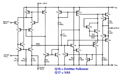
Have a look at resistor "R8" in the UA741 opamp from 1969.
_
Attachments
my apology to Mark
Mark, I felt uneasy upon a re-read of my response to your post. It comes across as curt and defensive. My apology if you took it that way.
Thanks for pointing out an early example of the VAS emitter resistor. It is a challenge to understand all that is going on in that design. Presumably a lot of the apparent complexity and gyrations have to due with the slow PNPs available at the time. I'm sure there have been a number of scholarly studies of that part. I seem to recall class notes from one of Thomas Lee EE classes that discussed it. Now I'll have to dig up those notes...
Best,
Jeff
Sorry to take this thread off topic but I found the class notes that I mentioned in the previous post (it's probably been linked here before):
http://web.stanford.edu/class/archive/ee/ee214/ee214.1032/Handouts/ho18opamp.pdf
http://web.stanford.edu/class/archive/ee/ee214/ee214.1032/Handouts/ho18opamp.pdf
Jeff, please don't worry about it, no offense taken.
IC guys also like emitter degeneration because it reduces the temperature dependence of gm ... the (kT/q) term is summed with a constant (Rdegen), reducing sensitivity to T.
I happen to know Tom Lee pretty well, Silicon Valley can be a small place sometimes. If you search very hard you might even find a couple of IEEE publications where we are coauthors.
Exactly? So you've introduced a ~12dB positive gain step to your open loop response which starts no higher than ~4kHz and finishes/plateaus no higher than ~14kHz.Yes exactly. I use 100 ohm bypassed with a capacitor or RC combination(0.33uF to 1uF and resistor around 33R) in all my CFA and explained it in OITPC thread OITPC - Output inclusive TPC (not TMC).
BR Damir
What is that supposed to do improve high frequency stability?
Exactly? So you've introduced a ~12dB positive gain step to your open loop response which starts no higher than ~4kHz and finishes/plateaus no higher than ~14kHz.
What is that supposed to do improve high frequency stability?
Please read post #9066 and look for the explanation in the tread OITPC (link in my post).
Your question for Bob prompted me to look up a few articles that specifically addressed this resistor.
Ed Cherry spoke often of the utility of a resistor in this position. The first reference to it in his writings that I'm aware of is "Feedback, Sensitivity, and Stability of Audio Power Amplifiers" which appeared in the JAES Vol 30 No 5 1982 May. Further reference to it appears in articles in Wireless World Jan 1995 and July 1997. In a nutshell, a resistor in that position 1) does not impact distortion (you might expect that it reduces OL gain and hence how much gain is available for feedback) , 2) improves stability (if properly choosen) and 3) allows for convenient current sensing of that stage. Cherry routinely used 68 ohms. Those WW articles were in part a response to the Doug Self articles (that formed the basis of his book) which might explain why in later editions Self includes the VAS emitter resistor.
Your observations are exactly correct.
Cheers,
Bob
One point that I haven't noticed Bob mention, and that Self seems to miss completely.
A resistor here makes it possible to add a bypass capacitor to put a zero into the feedback loop.
This can be very useful to shape the Return Ratio (feedback) in accordance with Bode's recommendations.
It permits better stability and/or more feedback for lower distortion.
Simple, reliable and low cost too.
Best wishes
David
Hi David,
You are correct, although I have never used a capacitor across the VAS emitter resistor for that purpose. I have instead, at times, put a small resistor in series with the Miller compensation capacitor to introduce a zero (and in theory eliminate a high-frequency right-half-plane zero that can be caused by feedforward through the Miller capacitor.
Cheers,
Bob
I did read post #9066. Your stated component values make no sense in the context of improving high frequency phase margin.Please read post #9066 and look for the explanation in the tread OITPC (link in my post).
Mark, I felt uneasy upon a re-read of my response to your post. It comes across as curt and defensive. My apology if you took it that way.
Thanks for pointing out an early example of the VAS emitter resistor. It is a challenge to understand all that is going on in that design. Presumably a lot of the apparent complexity and gyrations have to due with the slow PNPs available at the time. I'm sure there have been a number of scholarly studies of that part. I seem to recall class notes from one of Thomas Lee EE classes that discussed it. Now I'll have to dig up those notes...
Best,
Jeff
Yes, the lateral PNPs were quite bad, sometimes with current gain on the order of as little as 1. They were also very slow.
Another reason for the unique circuit architecture of the 741 was to avoid latch-up.
Cheers,
Bob
This is only half right. Assuming an conventional Miller-compensated VAS, no the global O/L gain will not be substantially effected, but the local loop gain of the VAS (as enclosed by the "Miller" compensation capacitor) will be very much effected. The emitter degeneration resistor aids VAS stability, after all by, lowering the local loop gain. And this does indeed have real potential to impact upon the amplifiers linearity primarily by reducing the amount of local negative feedback available for linearising the VAS.In a nutshell, a resistor in that position 1) does not impact distortion (you might expect that it reduces OL gain and hence how much gain is available for feedback).
Last edited:
- Home
- Amplifiers
- Solid State
- Bob Cordell's Power amplifier book