Bob,
It seems you have spent a great part of your life working with bjt, mosfets, jfet devices. You have engaged in in depth analysis of the inner workings of these items and formed educated reasonable opinions.
Has your research stopped at this point or will you continue on giving us accurate insight on newer items like the silicone carbide parts beginning to find there way into audio.
Also, were there any great advantages to the germanium transitors which can be found in many very old amplifiers. These are quite scarce now.
I would not find fault with a much do vacation at this time. It is not often we get a chance at direct communication with those more learned willing to share there experiences. A forum like this in Nikolai Tesla's time would have been enlightening to say the least.
Tad
")
Can I suggest a new rule for the Forum?
Every existing Member who has posted in the amplifier section must buy a copy.
A stab at a second rule would be.
All new Members must prove they have bought and read a copy before they are allowed to post in the amplifiers section.
Bob,
can I get a share in the royalties?
Every existing Member who has posted in the amplifier section must buy a copy.
A stab at a second rule would be.
All new Members must prove they have bought and read a copy before they are allowed to post in the amplifiers section.
Bob,
can I get a share in the royalties?


Hi Edmond,
Understand that until recently, commercially viable Mosfets were made by On Semi, IR and others. These are more suitable for inverters and such than music output stages.
-Chris
Hi Chris,
I have to disagree with you on one point. Although vertical MOSFETs were presumably designed for, and have found their greatest use in, switching applications, this by no means makes them any less suitable for audio (or any other application) than a device designed for audio (like lateral MOSFETs). It all depends on the parameters of the device and how one uses it. This would be like saying that an automotive relay is not good as a speaker relay; indeed, often they are (but it would be wrong to generalize this).
In fairness, there is another point to be made here. It is not just the device itself, it is somewhat how it is specified on the datasheet and how it is modeled in SPICE models. Here there may be some truth to the suggestion that the original area of application influences suitability for other applications. In many cases, the information on vertical MOSFET datasheets is switching-centric; a good example is the provision of gate-charge information which does not have an easily-interpreted relevance to an audio application. Another example is the unavailability of SPICE models that properly model subthreshold conduction. Yet another example is the cobbled models that are used to model the nonlinear gate-drain capacitance, some of which incorporate nonlinear elements into then like diodes.
Cheers,
Bob
Hi abraxalito,
[snip]
Keeping in mind what I know of Mr. Self's opinions gained from direct communication with him, Edmond's comments stated in the present tense are clearly not accurate.
[snip]
-Chris
Present tense, past tense or whatever tense, does it matter? I don't think so, as even the latest edition of his book (13 July 2009) contains exactly the same erroneous assumptions (read: prejudices) as the previous editions or articles in EW.
Well this thread has taken a turn.
Bob Cordell has been an active and helpful contributer to the DIY community. This thread started out as way to congratulate and encourage Mr Cordell.
Unfortunately, some have turned the thread into something else. That is unfortunate.
I look forward to buying a copy of the book and I am glad Mr Cordell contributes his wisdom to this forum
Indeed. Courtesy of Chris.Well this thread has taken a turn.
[snip]
Unfortunately, some have turned the thread into something else. That is unfortunate.
[snip]
edit: Maybe one of the moderators is willing to move the posts about MOSFETs vs BJTs where they belong: "Bob Cordell Interview: BJT vs. MOSFET"
Last edited:
Bob,
It seems you have spent a great part of your life working with bjt, mosfets, jfet devices. You have engaged in in depth analysis of the inner workings of these items and formed educated reasonable opinions.
Has your research stopped at this point or will you continue on giving us accurate insight on newer items like the silicone carbide parts beginning to find there way into audio.
Also, were there any great advantages to the germanium transitors which can be found in many very old amplifiers. These are quite scarce now.
I would not find fault with a much do vacation at this time. It is not often we get a chance at direct communication with those more learned willing to share there experiences. A forum like this in Nikolai Tesla's time would have been enlightening to say the least.
Tad
My dear wife Angela thinks I need a vacation too! She has put up with a lot during this time.
I worked a tiny bit with Germanium power transistors in my teen years, and never really liked them. It is fascinating that nowadays we have Silicon-Germanium bipolar transistors that are made to be extremely fast. The Silicon is doped with Germanium. Now, also, some of the fastest CMOS processes in 45 nm and below use silicon that is deliberately strained by some doping with Germanium.
I don't know where things will go with Silicon Carbide in things like power amplifiers. To the best of my knowledge, there is no P-type complement. For me, that is a show-stopper, but maybe not for others.
I'll never stop researching and learning. I'm just one heck of a curious guy.
Cheers,
Bob
To the best of my knowledge, there is no P-type complement. For me, that is a show-stopper, but maybe not for others.
Not a show-stopper for me.
The SiC JFETs, like vacuum tubes, don't come in P-Channel form. I wouldn't operate these at less than 300Vdc (otherwise the internal capacitance goes vertical). I'd use a final similar to this one. Getting the voltage up and current down also avoids another problem with these: a substantial gate current that accompanies higher Vgs bias voltages, due to a parasitic diode that turns on and begins to pull current.
Getting the durn things: now that's a show-stopper.
Attachments
Well this thread has taken a turn.
Bob Cordell has been an active and helpful contributer to the DIY community. This thread started out as way to congratulate and encourage Mr Cordell.
Unfortunately, some have turned the thread into something else. That is unfortunate.
I look forward to buying a copy of the book and I am glad Mr Cordell contributes his wisdom to this forum
I think that any topic in the book is fair game for this thread, but we need not get into arguments about the views of other authors that may be different. Transconductance droop of MOSFET class AB output stages is a real and valid concern (after all, I complained about it in 1983). At the same time, it is especially important to use MOSFET models that properly take into account sub-threshold conduction if one is doing distortion simulations of MOSFET amplifiers. I advocate EKV models in the book and show a fairly straightforward way to create them for power MOSFETs. My adventures with EKV models were directly inspired by Edmond and Andy_c.
Cheers,
Bob
Not a show-stopper for me.
The SiC JFETs, like vacuum tubes, don't come in P-Channel form. I wouldn't operate these at less than 300Vdc (otherwise the internal capacitance goes vertical). I'd use a final similar to this one. Getting the voltage up and current down also avoids another problem with these: a substantial gate current that accompanies higher Vgs bias voltages, due to a parasitic diode that turns on and begins to pull current.
Getting the durn things: now that's a show-stopper.
Hi Miles,
I actually had not been thinking of their application with output transformers, but you make a good point. The main thing I was referring to was the need to operate them in a quasi-complementary output stage, which I don't like.
If one is willing to spring for an output transformer, these devices may be a good choice for getting a more tube-like sound without the fuss of tubes. Of course, one can do the same thing today with high-voltage vertical MOSFETs.
With a vertical MOSFET design feeding an output transformer, I think that one needs to be very mindful of the rather high peak voltages involved unless one uses an output transformer with a smaller primary impedance rating than is normally seen with vacuum tubes.
Cheers,
Bob
Having said all that, if I had only one chance to make the best possible amplifier that would be judged on listening tests under real-world conditions, that amplifier would have a JFET front end, and a vertical MOSFET output stage, with BJTs in the middle. This amplifier would certainly not cost less, and it would probably produce more heat (but I'm assuming that this best shot at an amplifier would not be allowed to be class A). I can also say that it would not necessarily have to depend on error correction, nor would it necessarily do better in conventional lab testing with a resistive load.
Bob
Hello Bob,
Congratulation on your book and your contribution to audio.
I have some questions. The amp that you have "one chance to build" have you actually built it and tested it with people or is it just a gut feel thing you have after many years of building and listening tests you feel this is the approach you would take.
In terms of specs do you think this amp would have <=0.001% THD across the audio band or worse , or is absolute THD not that important as long as it the same across the entire audio band.
What front end ie CD player + DAC and speakers do you use for evaluation.
Regards
Arthur
Thanks, Arthur.
I have not built that "one amplifier to build", but I have built amplifiers with much the same philosophy. Probably the best example is the 125-watt amplifiers that I built for use in my Athena 3-1/2 way powered loudspeakers. Each loudspeaker has four of those amplifiers in it; one behind the tweeter, one behind the midrange and two behind a group of four 5-1/4 inch woofers.
Those amplifiers employ JFET inputs and an IPS/VAS much like the one I used in my MOSFET power amplifier with error correction. Each amplifier uses one pair of IRFP240/9240 output MOSFETs (enough to do 125W into a known, well-behaved load). The output pair is biased at about 150 mA. The amplifier does not use error correction, and has a gain crossover frequency of about 1 MHz. The amp does less than 0.03% THD-20 over its full range of power into 8 ohms.
Off the top of my head, the "one amplifier to build" would probably use four output pairs using the Toshiba MOSFETs, each biased at 200 mA and using the asymmetrical source resistor technique I describe in my book. The amplifier would probably be about 200W into 8 ohms. I'm guessing I would also use Transitional Miller Compensation. It would probably come in at between 0.001 and 0.003% THD at 20 kHz. It is not important to me that the amplifier has the same THD across the audio band. If this amplifier comes in at 0.0001% at 1 kHz I will not complain. Anything better than 0.003% at 20 kHz is probably gravy, especially if there is not too much high-order stuff in the residual. This amplifier would likely have extremely low distortion at low power levels and would exhibit little if any distortion increase as power is reduced from full power downward.
I usually use my M3 speakers for listening tests, as they are fairly low sensitivity, on the order of 84 dB, and they use nice Morel drivers. I use a Philips SACD player that is nothing special.
Cheers,
Bob
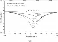
MOSFET vs BJT Wingspread
Attached is an interesting plot from my book that compares output stage wingspread simulations for a BJT output stage and a vertical MOSFET (IRFP240/9240) output stage, the latter biased at three different idle currents. Transconductance droop is evident in the MOSFET curves and BJT crossover wiggle is evident in the BJT curves.
MOSFET source resistors were added to equalize the output stage gain at high current for the two cases, but the MOSFET source resistor values were not adjusted in value or made asymmetrical to minimize crossover distortion.
It is interesting to note that the BJT crossover wiggle is somewhat more abrupt and occurring over a smaller range of output current, suggesting that the BJT may be more prone to create higher-order distortion products.
Obviously, MOSFETs like more bias current, and that is a price to be paid for good MOSFET output stage linearity. This will result in the amplifier running hotter in the idle state, but will have little influence on the maximum amplifier power dissipation that occurs in the neightborhood of 1/3 rated power.
Cheers,
Bob
Attachments
- Home
- Amplifiers
- Solid State
- Bob Cordell's Power amplifier book