Yes,..................... an argument that makes TMC very attractive for BJT amplifiers, and it may have little to do with static distortion measurements. It has more to do with what happens to crossover distortion under dynamic music conditions, where thermal bias mis-tracking may be poor, resulting in much worse crossover distortion than under static conditions (this is much less of a problem with MOSFETs). Here the use of TMC can mitigate some of the nasties of BJT output stages.
Ostripper has shown us that deliberately mis-tuning the output stage bias has a big effect on output distortion and that adding TMC mitigates the mis-tuning. That static mis-tuning is very roughly equivalent to dynamic bias mis-tracking.
Last edited:
Hi Carlos,
[snip]
As you know, I like MOSFET power amplifiers. However, due to transconductance droop, a MOSFET power amplifier with the same number of output pairs and idling at the same bias current will tend to have higher THD than a comparable BJT amplifier, at least in conventional bench tests. This was the reason I originally applied Hawksford Error Correction (HEC) to a MOSFET power amplifier - it did a wonderful job of mitigating the effects of transconductance droop. For similar reasons, I think TMC can be used to make the biggest difference in MOSFET power amplifiers; one then gets the benefits of MOSFETs and has THD-20 that is competitive with the best BJT amplifiers. One could always argue, of course, that one could apply TMC to a BJT amplifier and get still better THD performance.
There is, however, an argument that makes TMC very attractive for BJT amplifiers, and it may have little to do with static distortion measurements. It has more to do with what happens to crossover distortion under dynamic music conditions, where thermal bias mis-tracking may be poor, resulting in much worse crossover distortion than under static conditions (this is much less of a problem with MOSFETs). Here the use of TMC can mitigate some of the nasties of BJT output stages.
Cheers,
Bob
Hi Bob,
I think that TMC is most profitable in case of MOSFETs. Not only because of a larger transconductance droop compared to BJTs, but also because the content of the cross-over residual comprises harmonics of lower frequency (as the cross-over region is wider). At those frequencies TMC is more effective.
Cheers,
E.
edit: Just a thought. Correct me if I'm wrong.
Thank you Bob Cordell...long answer...nice text.
I have made tests about TMC...if you're interested you can see them here:
http://www.diyaudio.com/forums/soli...mkii-supercharged-release-28.html#post2398197
regards,
Carlos
I have made tests about TMC...if you're interested you can see them here:
http://www.diyaudio.com/forums/soli...mkii-supercharged-release-28.html#post2398197
regards,
Carlos
Yes,
Ostripper has shown us that deliberately mis-tuning the output stage bias has a big effect on output distortion and that adding TMC mitigates the mis-tuning. That static mis-tuning is very roughly equivalent to dynamic bias mis-tracking.
A TMC amp at 20ma (statically misbiased) sounds as good as a traditionally compensated amp with ideal bias. Really !
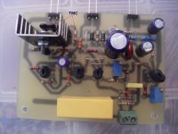
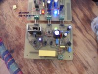
I now listen to the new BX (pix1) , which was designed around TMC , it is on a new level ....ABSOLUTELY stunning clarity(at normal bias). The nice thing is that I can just plug it in to my hitachi Lateral OP board .. (pix2).
The blameless has new life , one more pair of "strait" units , with CCS's , are being burned now.
")
OS
Attachments
Under short circuit, your flying catch diodes could keep the system with a fixed power dissipation until the junction reaches 150°C providing the time constants are right. Don't you think that this is a situation that can be accurately simulated using your TT thermal model.
If the short circuit aspect is solved, then one may design for a known load ( this is DIY ) by using a Zobel network that presents a near resistive load to the amplifier and there will be no 2° breakdown risk anymore ( see Leach model). Then the power only protection is enough
Is this correct?
A question on the operation of the flying catch diode ( fig 15.11 page 327)/
Is this a solution that has been tested in reality with BJT. Will it operate correctely whenever the short happens during any program signal with any phase, providing of course you can handle the limited power.
JPV
Hi JPV,
The use of the flying catch diodes in combination with temperature sensing using ThermalTrak diodes seems like a good one. The natural current limiting provided by the flying catch diodes gives the circuit time for other means to intervene before the output stage melts; I think in my book I mentioned fuses or circuit breakers, but some kind of cutoff actuated by the sense diode may be even better.
I've been using the flying catch diodes since 2003 with my MOSFET amplifiers. They are very effective, and a very simple way of providing natural current limiting. I believe that they have also tended to prevent additional collateral damage to circuits if an output MOSFET shorts out. I first used the flying catch diodes in the MOSFET power amplifiers that are built into my Athena active loudspeaker systems (described on my web site).
I have not used flying catch diodes with a BJT amplifier, but have simulated them with BJT designs and they work well. The flying catch diodes should provide approximately fixed current limiting at any point in the signal waveform. However, I don't think that they should be viewed as a form of protection against second breakdown.
Unless I have misunderstood, I don't see how a practical Zobel network would prevent signal voltage/current combinations that would create SOA problems. In many cases these signal combinations may occur at low frequencies in the neighborhood of woofer/enclosure resonances, where Zobels would seem to be impractical in size and maybe ineffective anyway.
Cheers,
Bob
Hi,
the reason for two-pole compensation is to extend the frequency response compared to the dominant-single-pole compensation. Two-pole compensation offers less stability than the dominant-pole compensation and requires careful implementation, even a small pole-zero mismatch can have high impact on time response.
Response time is inversely proportional to bandwidth. Terms like step response, frequency response, transient response, impulse response, peak time, rise time, settling time, slew rate, overshoot, ringing depend on bandwidth. The most objectionable distortions are time related, not at all amplitude related. Chasing the harmless harmonic distortion results in severely restricted bandwidth and amplifying device signal handling capability, hence, strongly raised distortions. THD does not distinguish between amplifiers, bandwidth does.
There`s nothing new about two-pole compensation whatsoever.

Hi JPV,
Unless I have misunderstood, I don't see how a practical Zobel network would prevent signal voltage/current combinations that would create SOA problems. In many cases these signal combinations may occur at low frequencies in the neighborhood of woofer/enclosure resonances, where Zobels would seem to be impractical in size and maybe ineffective anyway.
Cheers,
Bob
I am guessing that a matching network can transform the complex impedance of a speaker in a real one. Leach has a nice development in his book.
If the load is resistive, we can avoid second breakdown and limit only for power ie max Temp.
JPV
I am guessing that a matching network can transform the complex impedance of a speaker in a real one. Leach has a nice development in his book.
If the load is resistive, we can avoid second breakdown and limit only for power ie max Temp.
JPV
If I understand the "matching" plan correctly, the idea is to add conjugate shunt impedances so the load impedance looks like a pure resistor. Thus a normal 8 Ohm speaker load with its humps and dips would become perhaps a 4 Ohm resistive load. This makes the load on the amplifier much heavier, and increases crossover and large-signal distortion; I don't accept that it is a good plan. KEF did this with some of their loudspeakers a while back, but I believe dropped the idea completely, as customers weren't happy with the low impedance of the 4-Ohm speakers that were the result.
Last edited:
Hi,
the reason for two-pole compensation is to extend the frequency response compared to the dominant-single-pole compensation. Two-pole compensation offers less stability than the dominant-pole compensation and requires careful implementation, even a small pole-zero mismatch can have high impact on time response.
Response time is inversely proportional to bandwidth. Terms like step response, frequency response, transient response, impulse response, peak time, rise time, settling time, slew rate, overshoot, ringing depend on bandwidth. The most objectionable distortions are time related, not at all amplitude related. Chasing the harmless harmonic distortion results in severely restricted bandwidth and amplifying device signal handling capability, hence, strongly raised distortions. THD does not distinguish between amplifiers, bandwidth does.
There`s nothing new about two-pole compensation whatsoever.
Hi WuYit,
You are correct that there is nothing new about two-pole compensation. It goes at least as far back as Bell Labs in the early 70's when we called it "T compensation" and it was used to make better biquadratic active filters with the op amps of the time.
However, I don't think anyone here is claiming that TPC is new. The discussion of how it came about is really with respect to TMC.
I think that your statement that the most objectionable distortions are time-related is more of an opinion that is not shared by all equally. Moreover, it is a completely wrong generalization to suggest that chasing harmonic distortion to low levels restricts the bandwidth of amplifiers and hurts their signal handling capability.
Good time response and very low distortion are not in the least bit mutually exclusive.
BTW, when you refer to time distortion, it is important that you distinguish between time distortion that results from a linear process and time distortion that results from a nonlinear process.
Cheers,
Bob
TPC, while being generaly as efficient as TMC in respect of THD
reduction has somewhat a disadvantage in that the VAS loading
is heavier than in the TMC scheme, leading to lower OLG
before implementation of the compensation loops.
High OLG designs are naturaly displaying this difference in
a more visible way.
reduction has somewhat a disadvantage in that the VAS loading
is heavier than in the TMC scheme, leading to lower OLG
before implementation of the compensation loops.
High OLG designs are naturaly displaying this difference in
a more visible way.
Attachments
If I understand the "matching" plan correctly, the idea is to add conjugate shunt impedances so the load impedance looks like a pure resistor. Thus a normal 8 Ohm speaker load with its humps and dips would become perhaps a 4 Ohm resistive load. This makes the load on the amplifier much heavier, and increases crossover and large-signal distortion; I don't accept that it is a good plan. KEF did this with some of their loudspeakers a while back, but I believe dropped the idea completely, as customers weren't happy with the low impedance of the 4-Ohm speakers that were the result.
Yes it is the concept of conjugate network.
Leach has a network that can present exactly the resistive part of the loudspeaker in free air or in a closed boxe. One resistor capacitor shunt network compensates for the rising impedance ( taking into account the non linear voice coil inductance) and another shunt RLC circuit beeing a notch to compensate for the peak at resonance.
This would work nicely for dipoles or closed boxes. The Thevenin impedance seen from the loudspeaker is the impedance of the amplifier of course.
I have no practical experience with the circuit but as shown it can be designed without beeing a higher load than the nominal voice coil resistance which is as you said always lower than the impedance.
Of course the sine wave distortion ( large signal and crossover) is larger for a heavier load but this time we have a resistive load so less power stress.
Do you know what is the influence of the phase of a load on the distortion products of an amplifier
Tank you for your comments
JPV
TPC, while being generaly as efficient as TMC in respect of THD
reduction has somewhat a disadvantage in that the VAS loading
is heavier than in the TMC scheme, leading to lower OLG
before implementation of the compensation loops.
High OLG designs are naturaly displaying this difference in
a more visible way.
Hi wahab,
I'm not certain that it can be said that TPC is as efficient as TMC in reducing distortion all the time. I think it may depend on where the distortion is dominantly coming from. If the dominant source of distortion is in the output stage, TMC may do a better job of reducing the distortion than TPC for a given stability margin. I suspect that the more local nature of the TMC feedback around the output stage may allow its distortion reduction to extend to higher frequencies. Bear in mind that with TMC there are two loop gain crossover frequencies to deal with - the usual global one and the local compensation loop one (which I think can be a bit higher).
On the other hand, if the dominant source of distortion is in the IPS-VAS, TPC may do a better job. However, if your dominant source of distortion is in your IPS-VAS I recommend you do a better job on your IPS-VAS design.
Anyway, I have not looked at such a comparison in a long time - I'm just raising the question.
Cheers,
Bob
RE Doug Self's comment about KEF and customer unhappiness with 4 Ohm speakers:
Customers see on the back of the ordinary mass-market amplifier that it says 8 Ohms, then see on the speakers that they say 4 Ohms, and not knowing any better, they are worried that they are going to ruin something. Nobody has to change anything, just re-labeling the speakers works pretty well to allay concerns so that customers can just use the gear without fear. Every speaker maker has these issues and they deal with them differently, but I can tell you from vast personal experience working for Klipsch and a/d/s/, that as long as customers see two different numbers, you will NOT be able to tell them not to worry about it... they will worry about it.
Customers see on the back of the ordinary mass-market amplifier that it says 8 Ohms, then see on the speakers that they say 4 Ohms, and not knowing any better, they are worried that they are going to ruin something. Nobody has to change anything, just re-labeling the speakers works pretty well to allay concerns so that customers can just use the gear without fear. Every speaker maker has these issues and they deal with them differently, but I can tell you from vast personal experience working for Klipsch and a/d/s/, that as long as customers see two different numbers, you will NOT be able to tell them not to worry about it... they will worry about it.
RE Doug Self's comment about KEF and customer unhappiness with 4 Ohm speakers:
Customers see on the back of the ordinary mass-market amplifier that it says 8 Ohms, then see on the speakers that they say 4 Ohms, and not knowing any better, they are worried that they are going to ruin something. Nobody has to change anything, just re-labeling the speakers works pretty well to allay concerns so that customers can just use the gear without fear. Every speaker maker has these issues and they deal with them differently, but I can tell you from vast personal experience working for Klipsch and a/d/s/, that as long as customers see two different numbers, you will NOT be able to tell them not to worry about it... they will worry about it.
Hi Richiem,
I think that customers should worry about it if they want good sound. Too often speaker manufacturers cheat on their impedance specifications, having their minimum impedance dip well below the oft-accepted number of 63% of rated value. They do this to make them sound louder and get more effective efficiency with respect to 8 ohms. Amplifiers that don't say they can drive 4 ohms will almost surely do badly with a 4-ohm-rated loudspeaker. The amplifier will be shy on current capability and its protection circuits may come into play frequently.
It is truly unfortunate that many loudspeakers are designed on the assumption that they will be driven with a perfect voltage source capable of unlimited current delivery.
Cheers,
Bob
On two-pole compensation:
The Dymond and Mellor AES conference paper on two-pole compensation (TPC) has been made available in Another Thread:
http://www.diyaudio.com/forums/solid-state/94676-bob-cordell-interview-negative-feedback-307.html
I was reading it last night and was most impressed with it. Highly recommended.
As an infrequent visitor to these columns, I find it hard to track down all the relevant material on a given topic. I would like to think I had read everything relevant on TPC, but it is so scattered across threads that I am quite sure I've not seen even a fraction of it. It would be great if all the TPC posts could be copied into one thread, but I can see that would be a lot of work for somebody.
I have a couple of things to say on TPC myself. Should I start a new thread, or will that just confuse things further? What do you think?
On two-pole compensation:
The Dymond and Mellor AES conference paper on two-pole compensation (TPC) has been made available in Another Thread:
http://www.diyaudio.com/forums/solid-state/94676-bob-cordell-interview-negative-feedback-307.html
I was reading it last night and was most impressed with it. Highly recommended.
As an infrequent visitor to these columns, I find it hard to track down all the relevant material on a given topic. I would like to think I had read everything relevant on TPC, but it is so scattered across threads that I am quite sure I've not seen even a fraction of it. It would be great if all the TPC posts could be copied into one thread, but I can see that would be a lot of work for somebody.
I have a couple of things to say on TPC myself. Should I start a new thread, or will that just confuse things further? What do you think?
Hi Doug,
I heard the paper at the AES and spoke with the author. I too was impressed with it.
Here is a Devil's Advocate question I would like to see answered here:
Given that we have TMC, under what conditions, if any, should we prefer TPC?
My earlier post may have hinted at my opinion of a partial answer (e.g., use TPC when you have not done a good job on the IPS-VAS), but I'd like to see some more discussion of it.
Cheers,
Bob
My earlier post may have hinted at my opinion of a partial answer (e.g., use TPC when you have not done a good job on the IPS-VAS), but I'd like to see some more discussion of it.
Cheers,
Bob
Which post number was that?
Hi Bob,
thank you very much for your kind support in that particular post. I have not responded properly to your previous comments, which is impolite, but it is my intention to do that later on. My English is not what it should be, I`m struggling to express myself and it takes me an effort to write long posts. In some cases, a detailed elaboration would be beneficial and would excite less misunderstanding.
The current feedback topology has considerably more advantageous bandwidth properties and dynamic bandwidth behavior.
thank you very much for your kind support in that particular post. I have not responded properly to your previous comments, which is impolite, but it is my intention to do that later on. My English is not what it should be, I`m struggling to express myself and it takes me an effort to write long posts. In some cases, a detailed elaboration would be beneficial and would excite less misunderstanding.
Frankly, I was not thinking of TPC and your application. I don`t care much about the designations, it`s rather disturbing when people talk about non-existent effects.You are correct that there is nothing new about two-pole compensation. It goes at least as far back as Bell Labs in the early 70's when we called it "T compensation" and it was used to make better biquadratic active filters with the op amps of the time.
However, I don't think anyone here is claiming that TPC is new. The discussion of how it came about is really with respect to TMC.
Amplification device performance is fundamentally determined by time response (tubes being on top, bipolars on the bottom). So in a wider sense, all distortions, including amplitude distortion depend on time response. Ultimately, that is electric charge movement over time.Good time response and very low distortion are not in the least bit mutually exclusive.
Right, explanation is needed here.BTW, when you refer to time distortion, it is important that you distinguish between time distortion that results from a linear process and time distortion that results from a nonlinear process.
I`m aware of that, however, it does not make the statement less true.I think that your statement that the most objectionable distortions are time-related is more of an opinion that is not shared by all equally.
For the feedback function necessary higher amplifying device gain and the resulting lower amplifying device bandwidth mean reduced signal handling capability. In conjunction with time delay and poor separation between amplifying stages, it inevitably result in a progressive overdrive with associated phenomena. Multiple-stage feedback amplifiers cannot have high bandwidth (or a transparent sound stage, for that matter, because of poor harmonic representation, unfavorable harmonic distribution and massive phase errors).Moreover, it is a completely wrong generalization to suggest that chasing harmonic distortion to low levels restricts the bandwidth of amplifiers and hurts their signal handling capability.
The current feedback topology has considerably more advantageous bandwidth properties and dynamic bandwidth behavior.
Which post number was that?
Hi Doug,
That was post #973.
Cheers,
Bob
- Home
- Amplifiers
- Solid State
- Bob Cordell's Power amplifier book