Eva:
All documantation for which are you asking for is on the web Zesilova? 1000W/2000W, HQQ-55-505W-10-1 , but in Czech language, just use Google Translator. I also highly recommend for a better "understanding" also see the following thread: http://www.diyaudio.com/forums/solid-state/154104-topology-federmann-hqqf-55-a.html
All documantation for which are you asking for is on the web Zesilova? 1000W/2000W, HQQ-55-505W-10-1 , but in Czech language, just use Google Translator. I also highly recommend for a better "understanding" also see the following thread: http://www.diyaudio.com/forums/solid-state/154104-topology-federmann-hqqf-55-a.html
I wasn't able to find the schematic of the PCBs shown on your posts. However, I found similar schematics.
Since you seem to be aimed towards rack-mount medium-power professional audio amplifier style, I think that a few things are missing on your circuits:
- Short circuit protection (current limiting for a few sec, then mute if overcurrent condition persists)
- Protection against too low load impedance (same as above)
- Protection against RF on the output (oscillation)
- Driver transistors between the VAS and the output stage if needed. They are probably not strictly required, but are likely to result in a reduction of THD and output impedance at high frequencies (often overlooked, but high output impedance above 1khz results in speaker dependent tonal imbalance).
- Current limiting on the VAS or driver transistors to prevent damage to the VAS and drivers in case something becomes open or shorted on output stage, or in case input signal demands a too high slew rate.
- Protection against overheating (maybe fan control too). Required when using small heatsinks and relying on the low duty cycle of music signals.
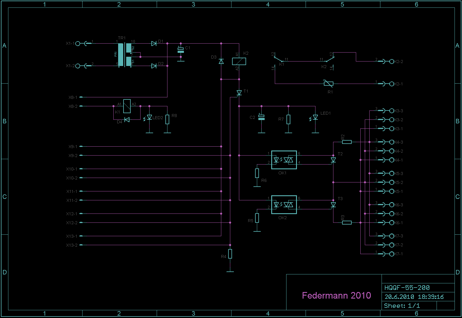
Current limitation is realized Zener diode.
Current is controlled by a separate module.
Eva:
All documantation for which are you asking for is on the web Zesilova? 1000W/2000W, HQQ-55-505W-10-1 , but in Czech language, just use Google Translator. I also highly recommend for a better "understanding" also see the following thread: http://www.diyaudio.com/forums/solid-state/154104-topology-federmann-hqqf-55-a.html
Topology federmann ?...
A bit exagerated to give his name to a topology
he didn t invent at all , apart perhaps in his wildest dreams...
I also highly recommend for a better "understanding" also see the following thread: http://www.diyaudio.com/forums/solid-state/154104-topology-federmann-hqqf-55-a.html
There are many attacks. There is no worthwhile text in http://www.diyaudio.com/forums/solid-state/154104-topology-federmann-hqqf-55-a.html
Last edited:
There are many attacks. There is no worthwhile text if http://www.diyaudio.com/forums/solid-state/154104-topology-federmann-hqqf-55-a.html
Not at all...
When some people point a shortfall in one of your design,
you dissmiss them as uncompetent.
The absence of drivers after the VAS, that is a source
of (a lot of) distorsion has been pointed
many times by many people and recently by Eva,
yet , you still are doing as if it s attacks rather than
following the councel of people that did experiment
these topology long before you yourself done it.....
I know well.these topology long before you yourself done it.....
I use overall feedback. I do not use local feedback. I use minimum transistor. This is my involvement varies.
Eva is good, they only attack Czech and Slovak friends.
Then you are surely the only one on earth that is still
Czech and Slovak at the same time....
Must explain why Eva appreciate you so much...
More comments after giving a quick read to the other thread:
If you have actually achieved 90dB open-loop gain all the way up to 10khz using one stage less than most people, then they are probably going to be angry, particularly the jealous ones. I like that kind of technical challenges. For example in one of my class D toys I get over 5kw @ 2 ohm for 1 second (before active limiting takes place, but music does not trigger the limiter) with just four pairs of TO-220 output devices.
The topology you are using has almost nothing new in it, I think it became popular in the early 1980s when MOSFET became in fashion and everybody wanted a MOSFET amplifier kit. The auxiliary supplies are a good idea and they are not very common, though.
Zener current limiting alone won't protect output stage against a short circuit for longer than a fraction of a second. The resulting dissipation is too high. It can only become reasonably reliable if the limiting condition is detected and the speaker relay is immediately opened for some time. This approach is often used in low-end amplifiers, but given the amount of them that I have repaired during the past 10 years, it's not 100% reliable.
Gate zeners (whatever purpose they are serving) need a series diode that is missing in your schematic. Without the series diode, and depending on idle (bias) Vgs and zener voltage, the upper zener may become forward biased before the lower zener becomes reverse biased and vice-versa.
Recommendation: Keep the zeners with added series diodes. Add a VI limiter, single or preferably dual slope, it does not take many parts or much space in SMD. You may develop these things in a separate breadboard or PCB attached to current amplifier PCB before laying out a PCB with all together.
Source resistors are not a bad thing. They can save a lot of MOSFET matching work, and something around 0.2 ohm won't degrade amplifier performance at all, but will actually help to linearize MOSFET.
Otherwise I like the unconventional layout and style. Old fashioned amplifier layouts and design philosophies discussed in most threads become extremely boring over time.
Topology federmann ?...
A bit exagerated to give his name to a topology
he didn t invent at all , apart perhaps in his wildest dreams...
F. claims that skilled constructors like Upupa Epops (P. Dudek) and PMA are fifty years on the blind way, e.g. he had declared on his web that Upupa's constructions were and are bad because before 18 years ago he did not used PC simulations e.t.c. , e.t.c. .....
Till today we have from F. only purely theoretical blablas, real amp was NOT till yet built....
I suggest you to read discussions on F. web through Google Translator and see..... its a pity that you would not understand text on screenshots done by F...
")
Federmann, your link is invalid, these is only "Sorry - no matches. Please try some different terms". Please be more careful in quoting
Federmann, your link is invalid, these is only "Sorry - no matches. Please try some different terms". Please be more careful in quoting
Here is the topic of the amplifier. What is the reason for your participation? Please choose a different thread. Why do you attack only on my thread?
From this schema I pressume that giving amplifier is not able to guarrantee full power of nominal sine output with load impedance and distortion at a nominal value of over than ten minutes because of heat and electrical unstability. There will be problems with oscilating and with temperature. I pressume that cooling is underdimensed. Have you measured on REAL, OPERATING AMP (not simulations) temperature of cooler?
What about EU safety rules in electronic?
What about EU safety rules in electronic?
Last edited:
Here is the topic of the amplifier. What is the reason for your participation? Please choose a different thread. Why do you attack only on my thread?
I am discussing just like others, because I am interesting in your project.... I am not atacking you....
Measure I said more than enough. Neither one simulation I did not.not simulations

- Status
- This old topic is closed. If you want to reopen this topic, contact a moderator using the "Report Post" button.
- Home
- Amplifiers
- Solid State
- amp 1000W/2000W, IRFP240/9240