Only if the sampling frequency is fast enough and the software doesn't suppress the oscillation.
Analogue scopes are far better than digital for this.
A 20MHz scope can still see a 50MHz oscillation even though it will be much bigger than the scope screen indicates.
But now that I see the pic, it looks more like a broken connection that is being affected by the heat.
Analogue scopes are far better than digital for this.
A 20MHz scope can still see a 50MHz oscillation even though it will be much bigger than the scope screen indicates.
But now that I see the pic, it looks more like a broken connection that is being affected by the heat.
Member
Joined 2009
Paid Member
i changed the r15 resistor on the baksa schematic (the 150ohm bias resistor) to 2 strings of 1n4001 ...
what have i done and is it stable?
I would worry about thermal stability - I'm not sure without running a simulation but you've pinned the dc voltage drop across the output device bases. I'm worried your Vbe circuit will not be able to fully control the dc-bias of the output. At low power, good heatsinks, relatively large emitter degeneration on the output devices (0R47), relatively large base stopper resistors (10R) and the fact that your diode string is at least sampling the ambient temperature - you'll probably get away with it for the most part but it's risky I think.
If there is no positive output voltage it sounds like the bootstrap is disconnected, because the bootstrap is what supplies the drive current for positive output. If the bootstrap capacitor gets hot it could be because the lower bootstrap resistors gets disconnected and then gives the bootstrap capacitor a DC voltage above it's limit. The upper resistor limits the current so the capacitor doesn't outright explode.
It may also be possible that the bootstrap capacitor has shorted internally and this would have similar symptoms. Check the voltage across the bootstrap cap to see if it is too high or too low.
I've have sometimes had solder micro-fractures that would cause a component to become disconnected without any visual sign.
Now, I understand completely the goal of AKSA 55. Hugh Dean love H2 distortion, to achieve this:
1. Unbalance the LTP.
He choose different value of resistors LTP's base at input and feedback. DC offset can be minimize using proper value of resistor LTP's colector (load) and resistor tail as current source.
2. Using resistor as LTP's current source.
This is create more H2 distortion, but more THD at high frequency.
I use this trick too, to "voicing" my amplifier.
3. Choose different value of resistors VAS's colector (bootstrap).
He need high enough slew rate, but not to high to my taste, so he use input inclusive compensation (according Douglas Self), so he can reduce the value of Miller compensation. He also use low Cob VAS transistor.
Then he use separate DC and AC feedback, to reduce noise and widen bandwidth a bit. For AC feedback, use small enough the value of resistor feedback.
I think, he do not like high damping factor, too. So, he choose resistor emitter of output transistor not too low, as I like.
Yes, this is AKSA concept. Distortion is H2 dominant in almost audio frequency, moderate slew rate, moderate damping factor, low enough noise.
But, I have different taste")
1. Unbalance the LTP.
He choose different value of resistors LTP's base at input and feedback. DC offset can be minimize using proper value of resistor LTP's colector (load) and resistor tail as current source.
2. Using resistor as LTP's current source.
This is create more H2 distortion, but more THD at high frequency.
I use this trick too, to "voicing" my amplifier.
3. Choose different value of resistors VAS's colector (bootstrap).
He need high enough slew rate, but not to high to my taste, so he use input inclusive compensation (according Douglas Self), so he can reduce the value of Miller compensation. He also use low Cob VAS transistor.
Then he use separate DC and AC feedback, to reduce noise and widen bandwidth a bit. For AC feedback, use small enough the value of resistor feedback.
I think, he do not like high damping factor, too. So, he choose resistor emitter of output transistor not too low, as I like.
Yes, this is AKSA concept. Distortion is H2 dominant in almost audio frequency, moderate slew rate, moderate damping factor, low enough noise.
But, I have different taste
Member
Joined 2009
Paid Member
The LTP is a complex animal. It has more than one way to generate harmonics. Read about the Gilbert cell for further clues to the sound and reason for resistor load for the LTP - think about the how the front end power supply interacts with the LTP when the VAS bootstrap and output stage are placing demands on the power rails. Simulations of simple sine wave into resistive load allows some detective work. But the final amplifier sound will depend on interaction of the output stage with the complex load of the speaker and the distortion profile will depend heavily on IM products from the full music signal.
The bootstrap VAS is another source of harmonics. Some of these factors can be frequency dependent too.
Then there is nested feedback considerations. The AKSA is amazingly complex. Sounds great too !
Are you sure about the mismatch base resistors - if you were to look at the original AKSA feedback network it contains several resistors, the effective impedance at the base of the feedback device is not that of a single resistor.
The trouble with the IM products is that it makes it more difficult to control the distortion profile and at higher volumes it can lose something of the sound. It also hampers the production of clean tight bass. With his next amp, the Lifeforce, the LTP was radically different and the distortion profile changed with a big jump in bass performance, a cleaner sound overall but in my personal opinion and based only on my clone version, the treble was too pronounced compared with the original AKSA. Later Hugh added the first Maya, which was a development from the Lifeforce and things just kept getting better and more refined. I keep coming back to the AKSA, it's just one of those amps you have to have in your collection
Last edited:
Are you sure about the mismatch base resistors - if you were to look at the original AKSA feedback network it contains several resistors, the effective impedance at the base of the feedback device is not that of a single resistor.
I'm sure he use separately DC and AC feedback.
You can try sim my thought and experiment about it
But the schematic is not the only one way to "voicing" an amplifier. I'm sure Hugh Dean will choose carbon resistor for feedback to add more H2 distortion.
For simple music with 3 instruments and vocal, it will sound very pleasing. But, for complex music with high dynamic, fast beat..... hmmmm. You can try your self.
Last edited:
Hi Bimo,
Not quite. The fb system is a three resistor network, and the effective resistor at the fb base is set identically to resistor on the input base.
Can I offer you a few ideas Bimo?
Distortion is inevitable, particularly PP AB SS amplifiers. Tubes, in plate load, start at around -45dB for H2. The AKSA is lower than -75dB down; you cannot describe this as serious distortion. You should work with it, and not regard it as the enemy. I do not see H2 as distortion; I see it as a musical harmonic. If you try to reduce it some nasty things happen, such as a skewed harmonic profile with highest levels of H3, which is 'detail' but not very musical.
I'm not sure about your Cdom issues, but yes, I use a good VAS transistor with very low Cob, only 2.5pF.
Too low Zout implies a very high fb factor. It also dries out the bass; there are many who like tubes amps for their bass and this got me thinking...... so my emitter resistors are 0.47R, quite high, and this reduces the gm of the output stage and seems to improve the crossover disjunction.
Low THD is an intellectual exercise and with global fb relatively easy to achieve. I also wanted to design an amp that sounded like a tube amp, but with real power. I do not claim this is ground breaking technology; it's relatively commonplace but it's another approach to a better musical amp, and should not be criticised as poor engineering. 95% of SS amps seek very low THD; I never wanted to follow the crowd, the result is the same as everyone else, and I even found an amp that really sounded musical. That surprised me as much as you, and Bigun gave the AKSA huge analysis and credits me with more design complexity I deserve. The AKSA remains a very good amplifier, and I still use many of the ideas in my more sophisticated designs.
Dengan Hormat,
Hugh
[/1. Unbalance the LTP.
He choose different value of resistors LTP's base at input and feedback. DC offset can be minimize using proper value of resistor LTP's colector (load) and resistor tail as current source.
Not quite. The fb system is a three resistor network, and the effective resistor at the fb base is set identically to resistor on the input base.
Correct, but there is another mechanism which brings back the sweetness to the top end. Some users reported that the top end was even better than the midrange.2. Using resistor as LTP's current source.
This is create more H2 distortion, but more THD at high frequency.
I use this trick too, to "voicing" my amplifier.
Yes, correct. Ratio of 1 to 1.5, 2k2:3k3.[/3. Choose different value of resistors VAS's collector (bootstrap)
Can I offer you a few ideas Bimo?
Distortion is inevitable, particularly PP AB SS amplifiers. Tubes, in plate load, start at around -45dB for H2. The AKSA is lower than -75dB down; you cannot describe this as serious distortion. You should work with it, and not regard it as the enemy. I do not see H2 as distortion; I see it as a musical harmonic. If you try to reduce it some nasty things happen, such as a skewed harmonic profile with highest levels of H3, which is 'detail' but not very musical.
I'm not sure about your Cdom issues, but yes, I use a good VAS transistor with very low Cob, only 2.5pF.
Too low Zout implies a very high fb factor. It also dries out the bass; there are many who like tubes amps for their bass and this got me thinking...... so my emitter resistors are 0.47R, quite high, and this reduces the gm of the output stage and seems to improve the crossover disjunction.
Low THD is an intellectual exercise and with global fb relatively easy to achieve. I also wanted to design an amp that sounded like a tube amp, but with real power. I do not claim this is ground breaking technology; it's relatively commonplace but it's another approach to a better musical amp, and should not be criticised as poor engineering. 95% of SS amps seek very low THD; I never wanted to follow the crowd, the result is the same as everyone else, and I even found an amp that really sounded musical. That surprised me as much as you, and Bigun gave the AKSA huge analysis and credits me with more design complexity I deserve. The AKSA remains a very good amplifier, and I still use many of the ideas in my more sophisticated designs.
Dengan Hormat,
Hugh
Last edited:
Hi Bimo,
The AKSA remains a very good amplifier, and I still use many of the ideas in my more sophisticated designs.
Dengan Hormat,
Hugh
I respect your design philosophy and others like Nelson Pass, John Curl, etc.
But I want to learn what design philosophy that suit for my taste.
Sometime, I design an amplifier to suit other person taste. But as an engineer, I do not mind.
Member
Joined 2009
Paid Member
I feel the same way - so much to learn from others, it's a lot of fun. Another amplifier that you might like to look at is the Naim NAP 140 and it's relatives. It uses a host of different tricks for another distinctive sound signature. It has a loyal following. It's quite a different sound than AKSA. So far I prefer the AKSA but I need to try out some different speakers and it's great to have both amplifiers in my collection to choose from.
Hi all
A note regarding the dominant H2 profile. The issue lies in the level of H2 required to sound good ALL kinds of music and not just small groups with acoustic instruments and natural voices (without Autotune, vade retro satana), keeping distortion low enough (much lower than with tubes).
75 dB or 85 dB better?
Ideally, it should be easily adjustable and thus be able to decide according to the type of music. Adjustable or with a selector: 75 dB -> 85 dB, or other values. It will be a winner. Two amps in one.
Last edited:
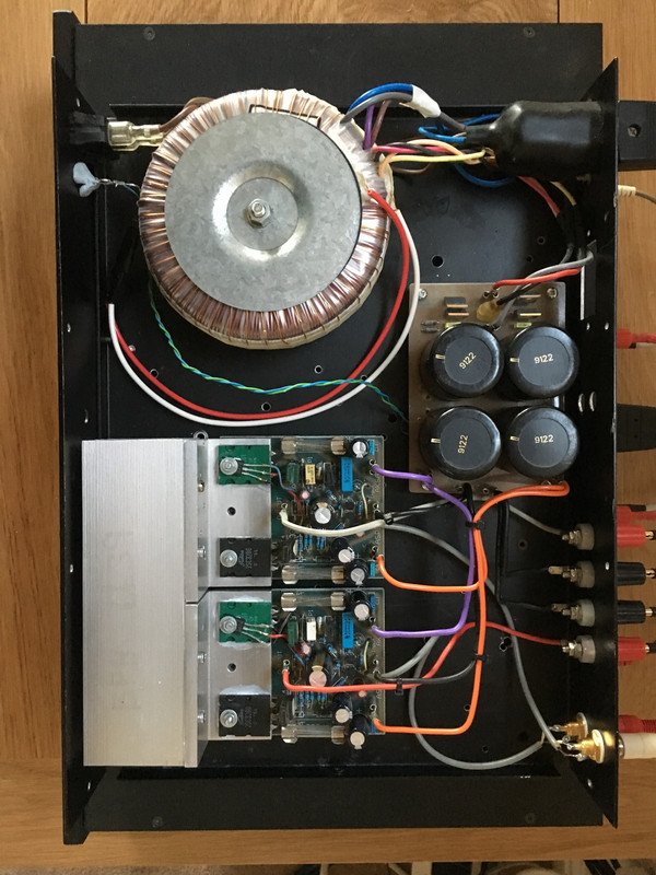
I plugged my P61N+/- into my main system the other day. It has been in a cupboard running my kitchen speakers for quite a few years. I think I originally built it about 18 years ago
I call it a P61N+/- because it started life as a P61, then got Nirvana'd, then got some N+ mods, but I didn't like all of them, hence the "-". It also been the mule for a couple of mods that Hugh asked me to evaluate - which were not successful.
Anyway, the point is that this is a VERY fine sounding amp!
Oh, and by the way, I know the secret
Last edited:
Member
Joined 2009
Paid Member
indeed, this amp was where it all started. I wanted to make a HT set up but the quote for 6 of these beasties was too high so I learned how to make my own, starting with a clone of this one. I never would have got into this hobby had it not been for AKSA 55 and the praise it was receiving from the likes of Carlos....
Member
Joined 2009
Paid Member
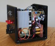
It will work fine, perhaps even sweeter - my first version built in 2009 and finalized in 2012 uses 27V rails. I think it has a better sound than my more recent 100W version providing you don’t push it hard on complex music.
Attachments
Member
Joined 2009
Paid Member
Aha, OK, many did not get built, it's one of the hazards of kits, I understand......
When you have it running, try a simple 680k resistor from collector of VAS to the fb node, base of T2. Gain will not be affected, but offset will be slightly altered.
Try it in, and without. See if you can tell the difference!
Hugh
When you have it running, try a simple 680k resistor from collector of VAS to the fb node, base of T2. Gain will not be affected, but offset will be slightly altered.
Try it in, and without. See if you can tell the difference!
Hugh
- Home
- Amplifiers
- Solid State
- Based on Hugh Dean's AKSA 55