Hi Jez
Fact is, I like the sound of those amplifiers and had to fix one. The pcb was in very bad shape caused by the heat produced by those resistors (it was toasted and with a hole under). The nearby regulators got so hot that the copper tracks under the pcb at which they were soldered got separated from the pcb, and the regulators were loose. The same thing happened to both my B200, exactly the same problem.
I remember thinking that it was a pity to have a good sounding device with so many problems and gave up on them (still keep them in a box).
I even started a thread
http://www.diyaudio.com/forums/solid-state/153008-mf-b200-bleeding-resistors.html
Hi infinia,
That's exactly what I was thinking. I wondered about these for a while after I saw the first unit, and this is the conclusion I came up with. I still don't know if it's a valid idea or not.
Hi anatech and Infinia
Probably you are right. It makes sense.
Thanks for your replies
Hi jmmartins,
Well, my views concerning a lack of output protection is well known. I think it's criminal for an amplifier not to have a way of disconnecting the load (your speakers) in the event of a fault. The side benefit of this is that it also provides on / off muting.
There are two ways to get them up and running again. The first is to take loads of pictures of the boards and complete units, then strip the PCBs completely and clean it up. You can now either make one big board, or break the board up into logical chunks. Use the old board as a guide and drill component holes. Clean the new board's copper side and remove any burrs. Use a resist pen and "connect the dots". Allow it to dry for an hour, then etch the PCB. Ferric chloride tends to be controllable etchant, float your new board copper side down. Move it now and again. With most PCBs, you will be able to see the pattern come up from the rear side. You do need good light. Remove, rinse the Ferric Chloride off and use lacquer thinner to remove your resist. You can use some liquid flux for electronic work to improve the wetting of the solder. Now, using your pictures as your guide, stuff the board again substituting new parts for old ones where you deem it should be done. Reinstall and presto! A new amplifier! So what do you think?
The other method involves using epoxy to patch holes, right through or not. Use a business card tapped tight up with a bit of oily plastic between the card and bottom of PCB. You can do the same with the top after putting the epoxy in. Stick the board between two flat surfaces large enough to cover the hole and put weight on. Come back tomorrow to finish up. You can trim excess epoxy with a razor blade (old type) and make it pretty flat and even with the board. Drill holes for leads if you need to. Replace copper traces with bits of component leads, or electrical wire with no insulation. The solid stuff, not stranded! Fix down with silicone after you have soldered everything up. Again, ta-da! A working amp.
Me? I'd make new boards, but broken up instead of one large one. Then I would redesign some bits. This is all doable with some patience. I've done it, you can do it.
-Chris
Well, my views concerning a lack of output protection is well known. I think it's criminal for an amplifier not to have a way of disconnecting the load (your speakers) in the event of a fault. The side benefit of this is that it also provides on / off muting.
I have seen many in the same condition. These amps were designed to fail after so many hours of use, depending on how hot the ambient temperature was.The pcb was in very bad shape caused by the heat produced by those resistors (it was toasted and with a hole under). The nearby regulators got so hot that the copper tracks under the pcb at which they were soldered got separated from the pcb, and the regulators were loose. The same thing happened to both my B200, exactly the same problem.
There are two ways to get them up and running again. The first is to take loads of pictures of the boards and complete units, then strip the PCBs completely and clean it up. You can now either make one big board, or break the board up into logical chunks. Use the old board as a guide and drill component holes. Clean the new board's copper side and remove any burrs. Use a resist pen and "connect the dots". Allow it to dry for an hour, then etch the PCB. Ferric chloride tends to be controllable etchant, float your new board copper side down. Move it now and again. With most PCBs, you will be able to see the pattern come up from the rear side. You do need good light. Remove, rinse the Ferric Chloride off and use lacquer thinner to remove your resist. You can use some liquid flux for electronic work to improve the wetting of the solder. Now, using your pictures as your guide, stuff the board again substituting new parts for old ones where you deem it should be done. Reinstall and presto! A new amplifier! So what do you think?
The other method involves using epoxy to patch holes, right through or not. Use a business card tapped tight up with a bit of oily plastic between the card and bottom of PCB. You can do the same with the top after putting the epoxy in. Stick the board between two flat surfaces large enough to cover the hole and put weight on. Come back tomorrow to finish up. You can trim excess epoxy with a razor blade (old type) and make it pretty flat and even with the board. Drill holes for leads if you need to. Replace copper traces with bits of component leads, or electrical wire with no insulation. The solid stuff, not stranded! Fix down with silicone after you have soldered everything up. Again, ta-da! A working amp.
Me? I'd make new boards, but broken up instead of one large one. Then I would redesign some bits. This is all doable with some patience. I've done it, you can do it.
-Chris
Let me guess,
It are Jamicon capacitors right? They are really bad anyway. Sadly enough, MF also put Jamicon electrolytics on several stages in series with the signal flow. Really almost anything would be better then those, so I suggest, modify them! The NE5532' which MF use everywhere are open for debate as well
With kind regards,
Bas
It are Jamicon capacitors right?
They are really bad anyway. Sadly enough, MF also put Jamicon electrolytics on several stages in series with the signal flow. Really almost anything would be better then those, so I suggest, modify them! The NE5532' which MF use everywhere are open for debate as well With kind regards,
Bas
It could be that the resistors are pre-loading the transformer keeping the rails regulation within some margin. So removing them might of been making it worse not considering the internal temp rise which is the real killer of caps. A better idea would be designing the output stage with higher idling bias and getting most of this heat out of the case. But that would take some real engineering skills.
Probably a too narrow mains line voltage spec is the real culprit I suppose. If MF specs it at all?
FWIW The price jump of 63V vs 80-100 V bulk caps is huge.
It was "typical" Musical fidelity to put huge power resistors in series with the power supply rails. After time they and their surrounding become al black.
With kind regards,
Bas
MF-Big Burned resistors
So you guys have actually not figured out why the big resistors were fitted from each rail to ground? The reason is that the poweramps, upon powering down, will discharge the main caps unevenly, due to a total lack of symmetry in the input stage. This leads to massive amounts DC offset, and subsequently nasty noises from the speakers. And complaints from irate customers.
Regards
Roar
Yes. I just said exactly the same thing in the B200 thread.....
DC voltage on F15 was +/-63V. PSU caps were 65V rated. Although the 2 Volt margin is that small, I don’t think that an 85V cap would do any good. It is solely a high temperature environment issue there IMHO).
That's strange, I have an F15 in front of my eyes and the caps are 15.000 uf 50V. DC voltage is supposed to be 45V - that's what the PCB says. The caps are funny looking (deformed). I have been trying to find the schematic on the net. No success. Anyone can help? I'm trying to figure out the input stage. Those tubes look just like JJ ECC83's but they are supposed to be 6922's.
Hi Cassiel
In the amp. I had on my bench, the cap rating and voltages were as I have written. You can have a look at the 3rd photo of my first post.
Besides, +/-45Vdc is not enough for the power output of the F15. (The amp. I tested, did deliver the specified power.)
I do not remember if I have made a drawing of the circuit. I am away from home now and I can't dig my repair notes. (Steve, the same applies for the photos you asked.)
George
got a pathetic response about them being rated to 10% above
Problem is that AC mains is rated +/-10% in much of the world - on a good day. I regularly see peaks of +15%.
That and ambient temperatures c. 100F make short work of "optimistically" rated electrolytics.
Having said that, it is rather expensive moving from 63V/50C/3,000hr to 75V/85C/10,000hrs.
Musical Fidility F15
Hi,
Can anyone help me to find the circuit diagram of Musical Fidelity F15 amplifier? It is very upsetting to see very poor manufacturing quality after opening the F15. There is 49volts dc at the output of the amplifier’s left channel. I don’t know whether the amplifier’s outputs are blown.
Many thanks
RK
Hi.
Have had an issue with a different amp, so has pulled the P150 into the audio system.
Has been running sweet, but have just read this thread and better check the caps. The P150 was bought new way back around 1990 by us.
Took the rear panel off the amp and could see the caps on that side. A small minor bulge on the caps, could just see them on the other side and no more than that:
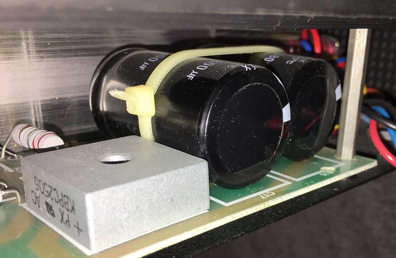
So, are these caps ok, and if they should be replaced, by the same or different caps? Any details available?
Cheers,
Have had an issue with a different amp, so has pulled the P150 into the audio system.
Has been running sweet, but have just read this thread and better check the caps. The P150 was bought new way back around 1990 by us.
Took the rear panel off the amp and could see the caps on that side. A small minor bulge on the caps, could just see them on the other side and no more than that:
So, are these caps ok, and if they should be replaced, by the same or different caps? Any details available?
Cheers,
Hi maf_au,
Test the bulge to see if the metal is flat underneath. If you can feel a flat surface by pressing in the bubble in the plastic you are okay. However, these amps can get pretty hot and it might be a good idea to buy replacements. When you do, look for ones rated at 125 °C, otherwise go with 105 °C capacitors. Look for high ripple current and the longer life when you do. The Digikey web site makes this information easy to find.
If you do feel the metal is bulged out, stop using the amplifier immediately. Wait for replacements to come in and install them before switching it on again. If you have ever seen a large capacitor vent, you'll understand why I am giving you this advice.
Best, Chris
Hi maf_au,
If you can get those capacitors in the high temperature rating, go for the 125 °C rating. Sorry about the expense, but the heat from these amps can make short work of the normal 85 °C capacitors. Your amplifier is a special case due to the heat build-up inside.
-Chris
If you can get those capacitors in the high temperature rating, go for the 125 °C rating. Sorry about the expense, but the heat from these amps can make short work of the normal 85 °C capacitors. Your amplifier is a special case due to the heat build-up inside.
-Chris
How are these caps, and any better ones available?
https://www.partsconnexion.com/media/pdfs/mundorf_ag.pdf
10,000uF 25V 25x35mm, 105C, ESR@100Hz:32
https://www.partsconnexion.com/media/pdfs/mundorf_ag.pdf
10,000uF 25V 25x35mm, 105C, ESR@100Hz:32
Those are great parts, didn’t realize they were of the higher temperature variety.
Not sure if you will realize an audible difference using those vs others however, since the filter capacitors are pretty far from the action, so not the best bang for the buck.
These are excellent, have used them also.
B41505A5109M000 EPCOS / TDK | Mouser
Not sure if you will realize an audible difference using those vs others however, since the filter capacitors are pretty far from the action, so not the best bang for the buck.
These are excellent, have used them also.
B41505A5109M000 EPCOS / TDK | Mouser
Last edited:
LOL. Had a better look at the caps in the P150:
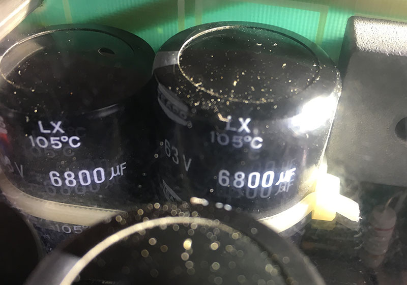
Big mistake before: not 10,000uF and not 25v and not 25x35mm!
They are actually 6800uF, 63v, 105C and 30x50mm
Haven't been able to find any higher temp caps than the original 105C
Also in the P150 amp, there are a bunch of 10 small caps, should they be replaced also?
10uF 16v, 100uF 63v, 470uF 16v
Big mistake before: not 10,000uF and not 25v and not 25x35mm!
They are actually 6800uF, 63v, 105C and 30x50mm
Haven't been able to find any higher temp caps than the original 105C
Also in the P150 amp, there are a bunch of 10 small caps, should they be replaced also?
10uF 16v, 100uF 63v, 470uF 16v
- Status
- This old topic is closed. If you want to reopen this topic, contact a moderator using the "Report Post" button.
- Home
- Amplifiers
- Solid State
- Musical Fidelity P150 owners take note!