Hello All,
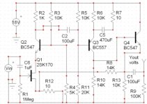
I'm currently in the process of assembling a low-noise measurement preamplifier (LNMP) with three gain stages (each 10x): AD797 > AD797 > LT1206. I'm planning on laying out the first two gain stages similar to the attached circuit taken from the book "Low-Noise Electronic System Design" by Motchenbacher and Connelly. However, since I intend to use this primarily for testing the noise of audio PSUs, I'd like to change the high-pass RC filter values (before the input stage and between the two input stages) to provide an fc of about 10Hz. Using the resistor values in the attached M-C circuit (10M before the input stage and 1M between the two stages), I've calculated cap values to be 1500pF (0.0015uF) and 0.015uF, respectively, to provide each filter with an fc of 10Hz.
Anyway, I've read that AC coupling the input can raise the noise floor of the preamplifer (see the first paragraph on page 3 of the Audioexpress article here: http://www.audioxpress.com/magsdirx/ax/addenda/media/colin2764.pdf). So my question is how does the size of the AC coupling capacitor effect the noise floor? In other words, can or should I adjust the value of the caps that I've calculated to reduce the noise added to the circuit?
Thanks,
Bryan
Attachments
AD745 is a fet input device, AD797 is a high bias bjt with 2.5 orders of magnitude more input current noise
"noise impedance", en/in is <500 Ohm for the 797, >100KOhm for the 745
for measuring low impedance ps use the 797 with much lower feedback, DC shunt R and big coupling C
op amp input current noise creates a noise V when it flows in the source impedance - for ps measurement with AD797 <100 Ohm DC shunt R could be justified
the 797 is much faster, with higher open loop gain than the AD745 and can be externally decompensated so 100x gain per stage is quite reasonable
If you are measuring noise on DC rails you might be advised to have some form of input protection. Connecting the input to a rail above or below the opamp supply (even if AC coupled) will degrade, if not damage the first device input stages.
The problem with caps and noise is that they can physically pick up interference due to their shape/construction.
If you don't need high input impedance FET's are not the best choice, something like an NE5534 would be much quieter at low impedances.
Cummulative effects of DC offset will be significant with cascaded high gain stages unless trimmed.
A low-noise measurement preamplifier (LNMP) with three gain stages (each 10x): AD797 > AD797 > LT1206.
Not a good plan. It is very difficult to make a 10x gain stage with low voltage noise because of the feedback network contribution. You'd better use a single 60 dB stage with a single AD797. The bandwidth should still suffice for audio frequency range measurements (otherwise use the decompensation pin) and distortion doesn't matter for that application.
I'd set the -3 dB point for the HP filter to about 1 Hz to give good accuracy at 10 Hz. The impedance of the network should be low to keep opamp current noise and thermal resistor noise contributions insignificant at low frequencies. I'd use e.g. 1k6 and 100 uF.
Samuel
I think three *10 stages will be quieter than a single *1000 stage.
The posted schematic is using two *33 stages for the same total gain and this was done to reduce the noise that would come from a single stage amplifier.
I suspect, with the correct chips/opamps in each stage, that the three stage will be quieter than the two stage.
The posted schematic is using two *33 stages for the same total gain and this was done to reduce the noise that would come from a single stage amplifier.
I suspect, with the correct chips/opamps in each stage, that the three stage will be quieter than the two stage.
The posted schematic is using two *33 stages for the same total gain and this was done to reduce the noise that would come from a single stage amplifier.
No. It's done for bandwidth reasons. Have you read the book the schematic is copied from?
I think three *10 stages will be quieter than a single *1000 stage.
I suspect, with the correct chips/opamps in each stage, that the three stage will be quieter than the two stage.
A second/third stage can't help adding noise--do the math, the difference can be several dBs.
Samuel
no.Have you read the book the schematic is copied from?
Thanks for the input.
Most all LNMP circuits using the AD797 use it in inverting mode. Which mode is preferable (inverting or non-inverting) for the AD797 in this application?
JCX mentioned using a bigger coupling capacitor. Is this to reduce noise or to adjust the fc?
Finally, with regard to Samuel's suggestion, if I use a single AD797 in non-inverting mode to provide 100X gain (bandwidth reduced to 100kHz using a cap in parallel with the feedback resistor), would external compensation be beneficial or necessary?
Thanks,
Bryan
The impedance of the network should be low to keep opamp current noise and thermal resistor noise contributions insignificant at low frequencies. I'd use e.g. 1k6 and 100 uF.
The Motchenbacher-Connelly book states that the LNMP should have hight input impedance so as not to load the circuit under test. Will the 1.6k resistor present too high of a load when measuring the performance of regulators or PSUs?
-Bryan
Will the 1.6k resistor present too high of a load when measuring the performance of regulators or PSUs?
Na. Standard PSU have below 1 Ohm output Z so 1k6 is entirely neglible.
Most all LNMP circuits using the AD797 use it in inverting mode. Which mode is preferable (inverting or non-inverting) for the AD797 in this application?
Most use it in inverting mode--sure..? I don't see many advantages for that. Non-inverting gives both lower noise and highe input Z, so that's the way to go.
Samuel
If I use a single AD797 in non-inverting mode to provide 100X gain (bandwidth reduced to 100 kHz using a cap in parallel with the feedback resistor), would external compensation be beneficial or necessary?
It might provide better PSRR, but with the feedback cap stability might become an issue if you decompensate the opamp. Just consult the datasheet, they give most of the details with this respect.
Samuel
Attached is the LNMP incorporating suggestions from the thread. The AD797 provides 100X and the LT1206 provides 10X. Low-value feedback resistors were used with the AD797 to reduce noise. Additionally, the bandwidth of the AD797 should be limited to 100kHz for PSU noise testing. The LT1206 implementation with Sallen-Key high pass filter were copied from Tangent's final stage in his LNMP seen here: Low Noise Measurement Preamplifier.
Any suggestions to further improve this circuit?
Any suggestions to further improve this circuit?
Attachments
I don't know how I missed this thread. Just built two different LNMPs, an opamp based one, from the Linear Technology app note 83
http://cds.linear.com/docs/Application%20Note/an83f.pdf
and the other one discreet, with four paralleled 2sk170v in the first stage, which isn't finished yet. The first one shows more noise than the discrete one. I'm very curious as to why Jim Williams in an83 has also built it in two stages instead of just one stage with 60dB gain. It's not like the guy doesn't know what he's doing. Puzzling.
input clamping diodes as mentioned earlier - 10 Ohms series would cut surge current when you connect that 100uF to the rail but does cost a little in the noise performance
Should the input clamping diodes go before or after the 1.6k resistor and 100uF cap?
Why doesn't the input clamping disturb the signal of interest (e.g., 10Hz to 100kHz) being amplified when it clips the higher-amplitude (presumably lower-frequency) signal?
Thanks,
Bryan
I don't know how I missed this thread. Just built two different LNMPs, an opamp based one, from the Linear Technology app note 83
http://cds.linear.com/docs/Application%20Note/an83f.pdf
and the other one discreet, with four paralleled 2sk170v in the first stage, which isn't finished yet. The first one shows more noise than the discrete one. I'm very curious as to why Jim Williams in an83 has also built it in two stages instead of just one stage with 60dB gain. It's not like the guy doesn't know what he's doing. Puzzling.
How are you measuring the noise of the LNMP? Are you just shorting the inputs?
Speaking of discrete, I really wanted to build the LNMP suggested by Fred (attached with discussion here: DIYHiFi.org • View topic - Cheaper alternative to AD797?) since it's so simple, but I have no idea how to properly limit its bandwidth.
-Bryan
Attachments
How are you measuring the noise of the LNMP? Are you just shorting the inputs?
Yes, and with a 50 ohm terminating cap. Then I measure the noise referred to the output.
Speaking of discrete, I really wanted to build the LNMP suggested by Fred (attached with discussion here: DIYHiFi.org • View topic - Cheaper alternative to AD797?) since it's so simple, but I have no idea how to properly limit its bandwidth.
-Bryan
See the filter at the output of the amp in the app note I linked before, that would work. It makes sense to filter after all stages, thus not introducing more noise in the critical first stage.
I think we're *really* missing detailed specifications here. Could you state:
* in what frequency range you want to measure
* what the expected source noise level is
* how you want to measure noise (e.g. RMS level, FFT...)
Otherwise we're just spiting out random suggestions which won't help you...
Well, I gave the answer before--its for bandwith reasons. LT1028 has 50 MHz GBW. At 60 dB gain response is 3 dB down at 50 kHz--not enough if you want to measure to 100 kHz.
After!
Indeed; and there is little point in spending much effort in the high pass filter. The important thing is accurate and steep low pass filtering as this has way more influence on the measurement result.
Samuel
* in what frequency range you want to measure
* what the expected source noise level is
* how you want to measure noise (e.g. RMS level, FFT...)
Otherwise we're just spiting out random suggestions which won't help you...
I'm very curious as to why Jim Williams in an83 has also built it in two stages instead of just one stage with 60dB gain. It's not like the guy doesn't know what he's doing. Puzzling.
Well, I gave the answer before--its for bandwith reasons. LT1028 has 50 MHz GBW. At 60 dB gain response is 3 dB down at 50 kHz--not enough if you want to measure to 100 kHz.
Should the input clamping diodes go before or after the 1.6k resistor and 100uF cap?
After!
It makes sense to filter after all stages, thus not introducing more noise in the critical first stage.
Indeed; and there is little point in spending much effort in the high pass filter. The important thing is accurate and steep low pass filtering as this has way more influence on the measurement result.
Samuel
- Status
- This old topic is closed. If you want to reopen this topic, contact a moderator using the "Report Post" button.
- Home
- Amplifiers
- Solid State
- Filters For Low-Noise Measurement Preamplifier