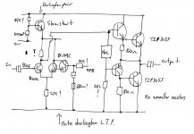
This amplifier appeared in Practical Wireless in 1978 ? and was designed by a B.C. Toms ? It went under the name of the "Europa" and the power amp I have drawn in outline from memory... the preamp was awful, used an LM381AN that was spectacularly bad on all fronts.
I built this at the time, the first "proper" amp I made from scratch and always remember the wonderful musical sound it seemed to have (without the preamp). It was AC coupled and ran on a 56 volt rail.
Aside from it being a quasi design look at the input stage and the darlington arrangement on the "inverting" input to the amp. At the time I didn't think it particularly odd, but of course it is. I have never seen this done before, the "balance" of the stage must be awful, but how would that arrangement affect the distribution of harmonics etc. It sounded good though.
Attachments
hello Mooly,
don't you think that the NPN transistor that you sketched in the power amplifier as darlington on the inverting input, was in reality a PNP transistor connected as voltage gain stage, with the emitter connected to the positive suppy rail, the base connected to the collector of the inverting input, and the collector connected to the upper side of the bias generator ?
Also, there may have been a bootstrap capacitor, for increasing the open-loop gain of the PNP voltage gain stage.
I don't agree with you regarding the LM381, especially the "A" version exhibiting a very low noise. You say it was spectaculary bad on all fronts. That was maybe the application, but surely not the chip itself.
The LM381 was the "deluxe" version of the LM387. The LM381 was packaged in a 14-pin DIL, getting access to the compensation capacitor for tailoring the open-loop gain at your will. When was it last time you could use such feature ? Do you know any recent audio-opamp providing access to the compensating cap for tailoring at your will the open-loop gain curve ? You may find some de-compensated versions of some good audio opamps, but do you have access to the compensation cap terminals ?
The LM387 was the same inside, packed into a 8-pin DIL, without acess to the compensation cap terminals. Please note the specific pinout, not the same as nowadays dual opamps.
Back in those times, National Semi had the great ambition of setting an industry standard regarding single supply audio opamps. Unfortunately, nobody followed them. I think the LM381 and LM387 never got multisource. I think that during all those years, National Semicionductor was the sole and only supplier of those very first audio opamps. Why was the LM381 not multisource ? Was there a hidden failure ? Patents issue maybe, with National Semiconductor raising the financial requirements too high ?
In the early eighties, I made tape preamps and RIAA preamps using LM381 chips, and the sound was an order of magnitude better than the sound coming from discrete designs using 2 or 3 transistors. On top of this subjective opinion, the measurements were all in favour of LM381-based preamps : lower power supply hum, lower noise, less distorsion and lower output impedance. Another advantage of the LM381 over contemporary audio opamp based solutions like µA709, µA741, LM358 and LM1458, was the built-in voltage reference used to set the DC output level in the LM381 and LM387. Of course, some calculations were needed for taking advantage of this, like ensuring a proper DC-gain for biasing the output at half the supply voltage. Most do-it-yourself people didn't have the technical background to do this. There was no internet for spreading the info, and the datasheets were not so widely distributed. A must-have was the audio amplifier cookbook, edited by National Semiconductor. But who could afford buying it ? As a consequence, most do-it-yourself people were judging the feedback networks used in the LM381 - LM387 as complicated and suspicious, because in this case, there must be a proper DC-gain for setting the output at half the supply voltage.
In my opinion, the LM381 is still a good solution when needing to amplify audio signals when there is a single power supply. Try making your own preamp using a single power supply, and you will quickly discover that the LM381 is embedding everything you need, in a clean, proper way. How many components will you use for getting a 120dB power supply ripple rejection ? How many components will you need for having a proper, low noise differential pair at the input, a good open-loop gain, and an output stage with a low output impedance, able to sink and source several milliamps ?
Imagine you are using a nominal 12V power supply, that may occasionally drop to 8V in case of discharged batteries. You may think that an optimal solution would be to use a NE5534 or OPA134 audio opamp, fed by a 7808 power supply regulator, feeding a double diode + decoupling capacitor for getting an ultra-stable low noise bias voltage. Try it. It won't work. Because the 7808 regulator needs at least a 2V drop for its own purpose. You'll need a more expensive low-drop 8V voltage regulator. And, if you operate a NE5534 or OPA134 using a single 8V supply, you will get degraded performance. Those excellent circuits need at least 10V in total, if you want to play safe. With most opamps, you can't DC bias the input so close to the negative rail, only using two diode voltage drops. With a NE5534, a OPA134 or a TL071, if you bias the input stage at 1.3V like the LM381 LM387 are, the circuit won't even start working. The only possible substitute is the LM358, having an input stage accepting a common mode voltage that includes the negative supply. The LM1458, widely used in +12V powered equipments, can't cope with inputs biased at +1.3V.
Now you better understand why an excellent circuit like the LM381 LM387 can get a negative fame. Those ones that don't understand its features (non standard pinout, built-in 1.3 V DC bias on the non-inverting input) can't use it properly.
The reason why the LM381 is not anymore used, is that nearly all audio solutions are using symetric power supplies like +12V and -12V nowadays, hence not needing anymore a super-stable bias voltage generator inside.
The first circuit that was better than the LM381, also designed for audio and also equipped with an audio-optimized low noise differential pair at the input, was the NE5534, NE5533 and NE5532. It came just in time when hifi equipment and professional audio equipent adopted symetric power supplies.
The LM381 LM387 is still unbeatable when using portable equipment, powered by 12V that can drop to 8V on discharged batteries, with a high supply voltage ripple appearing at 100 Hz or 120 Hz, when the equimpent gets connected on the mains using his poorly regulated mains power supply.
But, in this context, who really cares about quality ?
Actually, the LM381 LM387 are nearly too good for those remaining applications. Believe me, if you buy second-hand vintage portable audio equimpent, and if you find LM381 or LM387 inside, you can be sure that the ones having designed that portable equipment, made no compromises regarding the quality, and wanted to deliver the best possible quality.
You may tell me "okay, but nowadays they'll use a switched power supply, able to run from 6V to 18V, and delivering a symmetric +12V -12V power supply, enabling to use top-notch audio opamps like the OPA134 and some others". Let me be very clear about this. If you do this, you will fail. You you will decrease the battery life as the switched power supply makes you wasting miliwatts. Secondly, a +12V -12V supply is twice the wattage of a single supply nominal 12V. Thirdly, your switched power supply will generate high frequency pollution, meaning that if your equipment is a radio or a TV (LW, MW, SW, VHF, UHF), the sensitivity will be negatively impacted. So, where is the progress ?
You may tell me "okay, but what if I use a +5V analog power supply, and dedicated audio opamps able to run on a single +5V power supply ?" Then I would say YES provided you manage to design an ultra-stable ultra-decoupled 2.5 V reference voltage, or a virtual ground. The +5V power supply standard and dedicated +5V audio opamps are the real LM381 LM387 killers. Use a +5V supply everywhere in the equipment, so you can use a 4-cell rechargeable NiMH battery at 4.8V when battery operated. And, avoid the switched power supply temptation if you want to get the best sensitivity in case you are designing a portable radio.
Then you may say goodbye to the beloved LM381 LM387, no shame, no fuzz, that's evolution.
So, next time you say the LM381 is bad on all aspect, expect the LM381 design team ringing at your door, wanting some explanations from you, the hard way.
I'm attaching some datasheets, in case you miss them.
Cheers,
Steph
Attachments
Last edited:
Hi Mooly, Steph may be right about the circuit of the inverting input. It certainly doesn't seem warranted there. If it comes from a schematic, there may be an error there. It would not be the first time draughting and PCB designs disagreed.
This is unashamedly a 2 stage design and difficult to analyse owing to the dual roles of the driver transistor. However it is often good to read the background to a design in order to understand why and how these crazy topologies arose.
Access to JLH's 2-stage design details might shed some light on this design. It may well just be Toms' take it. Although the Doctor may be unimpressed with the type, he is probably well aware and may care to comment on the background issues.
My efforts with a 2 stage design in the late 70s were not really succesful either. The DC offset was unstable and even harmonics gushed from the speakers. I think it had a 200 ohm balance pot. between the input stage emitters to help. That may well be the genesis of the "niceness" control! Many today like a small measure of low order, even harmonic distortion in music reproduction and pay very high ticket prices for it.
This was not always the case. Just for the record, do you recall the driver types and can you get a value for that single tail resistor?
best regards
From my personal experience, the worst do-it-yourself preamp that ever existed is the Sinclair Stereo Sixty from Sinclair, especially when fitted with the "AFU" option (Active Filter Unit). This is dating back from 1969.
It is a single supply design, using discrete transistors. There were 2 NPN silicon transistors at the input with a switched feedback network for configuring it in linear low gain or RIAA high gain. At first glance, this looks stupid, as for the line input it is better to bypass any active circuitry. Then there was a NPN silicon transistor as active Baxandall tone control. Actually, the use of the preamp even on a line input was justified by the need of a low impedance source for the active Baxandall. This avoided the need for a dedicated emitter follower, just before the active Baxandall. Economy was the name of the game. One transistor less. Thank you Sir Clive.
There were no real potentiometers inside. Instead, vertical trimmers were used, with the trimmers of the two channels being coupled using a mechanical axle, as most of the controls (bass, treble, volume) were common to the two channels. The trimmers have a very limited cycle lifetime. They are not designed for being operated on a daily base. They quickly get erratic, the cursor losing pressure and the conductive path getting eroded. On top of this, the mechanical axle had a tendency to twist. As a consequence, with the time passing there was a nasty left-right volume imbalance developing, like one channel vanishing. It made the operation of the pream quite uncertain. I thus needed to open the amplifier, and reshape the coupling axle, untwisting it. Another annoyance caused by the use of trimmers instead of potentiometers, was the fact that the trimmers had a linear progression, instead of the log progression of the volume potentiometers. Clive Sinclair used the trick of loading the 47K linear volume trimmer by a 10K resistor (the balance trimmer half-way), and this gives indeed a simulacre of a log progression at intermediate levels. But before 1/5 turn, at low level, the progression is still linear, because the equivalent resitance of the volume source is much lower than the 10K load. And we, like you, are using our amps at low level. Meaning that the progression of the volume is odd, at normal listening levels.
Then there was the AFU option. Butterworth filters, 2th order, with a variable frequency corner, using one emitter follower BJT as active device, and vertical trimpots in the feedback networks. One 2nd order high-pass as variable rumble active filter, followed by one 2nd order low-pass as variable active scratch filter. There was a design failure inside the AFU. The base current of the two emitter followers was flowing through the cursor of the vertical trimmers. If you were touching the controls, you were getting a huge "scratch" in the loudspeaker. After a few years, in some occasions, we got a continuous scratch emission due to oxydation. We then throwed away the AFU, for getting a more useable preamp. Anyway, those problems forced me to dig into the schematic, around 1975, and the "Sinclair Project 60 Instructions" booklet (well organized, excellent pedagogy) was actually my first contact with electronics. Thanks again, Sir Clive !
During years, I asked myself why after removing the AFU, the bass looked less punchy. During years I had the diffuse feeling that some electronics can add magic to the sound, enhancing it in a strange way. It is untill recentlly, after having modelled the circuit under LTspiceIV, that I discovered that the high-pass section of the AFU was not set as a Butterworth (Q = 0.707), but set with a Q factor equal to 1.3, meaning that my perception was right. Must say this fact is another Sinclair annoyance, as the instruction manual never metionned that the AFU was there, not to combat rumble, but to add some punch to the bass when set just below the corner frequency of the loudspeaker. Quite an useful, undisclosed feature ! Because when purchasing the AFu option, the schematics were not included. I had to reconstruct the AFU schematics, from the physical PCB and physical module. It is only this way that you realize that the values of the components don't make a high-pass Butterworth.
Any experienced electronician would have critized the AFU option, to death, including the press maybe, if the schematics of the AFU option was disclosed by Sinclair back in 1969. I guess Sir Clive would have been pressed to release a version 2, before putting it on the market, in order to avoid the press condemning the failures of such design. With reason.
It is amazing, however, to see that the press did no critics about the preamp, and the use of trimmers instead of real potentiometers. I think that the press got positively impressed by the fact that the trimmers enabled Sinclair to avoid any cabling. But that was a misconception, as back in 1969, there were already designs having their real good potentiometers soldered on the main PCB, avoiding any cabling. So you see, Clive Sinclair strategy was cost cutting, cost cutting, and cost cutting. Nothing more, and nothing else.
I'll be very glad if somebody post pictures of preamps dating back before 1969, having their potentiometers soldered on the main PCB hence avoiding any cabling. Commercial preamps and diy-preamps.
Now, having said all this, what were the issues with your preamp ? Shall we open a competition, "the worst audio preamp" diyAudio thread ?
Cheers,
Steph
Last edited:
Hi steph_tsf,
Actually you have spotted an ommision on my part... yes I have indeed missed the VAS stage out, just as you say a PNP device. That's going to confuse everyone.
The 2 BC109C transistors were as shown though in that darlington arrangement.
Try as I might I have not turned up a copy of the circuit on the net.
Thanks for the links to")
That LM381AN... that was the super ultra low noise version wasn't it. It really seemed the weak link in the design. At the time I had just built the "Purbeck" 'scope also in PW and was able to confirm the poor assymetrical clipping (and what at the time seemed weird artifacts, as out level increased). It would be interesting to revisit the design after all these years. Think I still have some LM381's somewhere.
Actually you have spotted an ommision on my part... yes I have indeed missed the VAS stage out, just as you say a PNP device. That's going to confuse everyone.
The 2 BC109C transistors were as shown though in that darlington arrangement.
Try as I might I have not turned up a copy of the circuit on the net.
Thanks for the links to
That LM381AN... that was the super ultra low noise version wasn't it. It really seemed the weak link in the design. At the time I had just built the "Purbeck" 'scope also in PW and was able to confirm the poor assymetrical clipping (and what at the time seemed weird artifacts, as out level increased). It would be interesting to revisit the design after all these years. Think I still have some LM381's somewhere.
Ian,
As you'll see above I made an ommision on the circuit (didn't show the VAS).
Device types... I think it was a BFY51 and BC461 for the drivers and another 461 for the VAS. The vbe multiplyer was TIP31 ?
The tail resistor was high... I'm going from memory 30 years ago. Could it be 6K8 ? Now if someone had a copy of the mag, that would be great.
As you'll see above I made an ommision on the circuit (didn't show the VAS).Device types... I think it was a BFY51 and BC461 for the drivers and another 461 for the VAS. The vbe multiplyer was TIP31 ?
The tail resistor was high... I'm going from memory 30 years ago. Could it be 6K8 ? Now if someone had a copy of the mag, that would be great.
Assymetric clipping. I guess that your application was using the LM381 in a low gain application. Maybe a unity gain buffer. The LM381 can't cope with small gains leading to high amplitudes on the input stage. Because the input is fixed-biased at 1.3V above ground. If you use it as an unity gain buffer, for line-level signals, you'll overdrive the input stage. There is no voltage remaining on the negative swing, for biasing the long tailed input pair. The LM381 got designed for high gain, hence small voltage swings on his inputs. I'm now realizing that the LM381 LM387 can't be used without special precaution, as from previous example, as line-level unity gain buffer for delivering a low impedance to a Baxandall tone corrector. That's maybe possible using an inverting configuration with no common mode swing applied to the differential pair. Once you know how to do this with a LM381, then you can do everything including using it as negative gain block for the Baxandall itself, and anything else with moderate gain. You'll end-up having a chain of inverting amps. That's quite uncommon. Surely an experienced professional will be able to do this. But not a do-it-yourself occasional hobbyist in the early eighties. This may have caused the poor reputation of the LM381 and LM387. Plus the fact that, maybe, the LM381 was compensated for high gains, hence needing to calculate the external compensation that's needed for moderate and low gains. If the compensation is not properly done, you may get an amplifier that behave okay on a 4.7K load in the lab, and that tends to oscillate when connected on higher loads like 22K to 100K, or connected to long cinch cables exhibiting capacitance.That LM381AN... that was the super ultra low noise version wasn't it. It really seemed the weak link in the design. At the time I had just built the "Purbeck" 'scope also in PW and was able to confirm the poor assymetrical clipping (and what at the time seemed weird artifacts, as out level increased). It would be interesting to revisit the design after all these years. Think I still have some LM381's somewhere.
That's jogged my memory... yes the preamp had comprehensive inputs, everything from tape head I think, to moving coil and of course line level inputs. There was even a PCB produced at the time, the whole amp, pre and power all fitted on the one board. To me at the time it was really impressive.
You mention tone controls, yes it had a passive Baxandall arrangement.
You mention tone controls, yes it had a passive Baxandall arrangement.
The articles must have been in March and April 1978 as this mentions it, but this wasn't the cover I remember, that had a picture of the amp on it. This was the 'scope though, that got me started on all this all that time ago,
http://cgi.ebay.co.uk/Practical-Wir...temQQimsxq20100313?IMSfp=TL100313138002r12735
scroll down page
http://cgi.ebay.co.uk/Practical-Wir...temQQimsxq20100313?IMSfp=TL100313138002r12735
scroll down page
Hey, that was a cool looking scope for 1978 DIY! Was it a 3BP1 or later Philips DG7... series tube inside?
Mooly, I can't be certain but the types you recall seem right for the availability, economical restraints, the UK spares market and magazine projects of the day. The TIP 31 seems a bit expensive for the Vbe mult. role and there would have been some decent heatsinking on the TO5/39 transistors, no? You guys always seemed to get raw deals on components and the magazine designs seemed constrained by that. With the encouragement of 'Elektor' and the demise of local mags that has all changed though, I thinkl!
Sadly, we need either a windfall from Ebay's offerings or for the guys who do recall the design to get on thread. Good luck guys, it's an interesting quest.
best regards
You are spot on Ian
A 3BP1, and running at around 800 volts I seem to remember. Zener stabilised HT.
I got the proper case for it, but made all my own boards to the designs in the mag. It used point to point wiring on the main X and Y amps on a large ground plane PCB. 6mhz bandwidth... it was great. I had just started college at the time... radio and TV course
The Europa... clip on heatsinks for the drivers and VAS. The VBE multiplier was a flat pack to mount next to the outputs on the chassis. At the time of course I was much less sure of my abilities and substituting and tweaking. I remember the dreaded preamp and realising it sounded better with the inputs reduced in level, but then it wasn't quite loud enough, so I tried rigging a 741 as a simple x3 or whatever gain stage. It was weeks later I came to understand that altering the feedback on the main could alter the gain... and that you could actually calculate such things.
Things moved on quickly after that... learning learning all the time, at work (TV engineer) and at play.
Built a Radford ZD22 and HD250... some JLH's... and still didn't fully understand grounding... they always had residual hum.
And I'm still learning now and the amps are silent now... no hum.
A 3BP1, and running at around 800 volts I seem to remember. Zener stabilised HT.
I got the proper case for it, but made all my own boards to the designs in the mag. It used point to point wiring on the main X and Y amps on a large ground plane PCB. 6mhz bandwidth... it was great. I had just started college at the time... radio and TV course
The Europa... clip on heatsinks for the drivers and VAS. The VBE multiplier was a flat pack to mount next to the outputs on the chassis. At the time of course I was much less sure of my abilities and substituting and tweaking. I remember the dreaded preamp
and realising it sounded better with the inputs reduced in level, but then it wasn't quite loud enough, so I tried rigging a 741 as a simple x3 or whatever gain stage. It was weeks later I came to understand that altering the feedback on the main could alter the gain... and that you could actually calculate such things.Things moved on quickly after that... learning learning all the time, at work (TV engineer) and at play.
Built a Radford ZD22 and HD250... some JLH's... and still didn't fully understand grounding... they always had residual hum.
And I'm still learning now
and the amps are silent now... no hum.Hi Mooly, Steph may be right about the circuit of the inverting input. It certainly doesn't seem warranted there. If it comes from a schematic, there may be an error there. It would not be the first time draughting and PCB designs disagreed.
best regards
Quite often in those days PCB's were tape on a clear sheet.
These days with error checking there shouldnt be any differences between schematic and PCB. My CAD package has an integrity checker.
I also found I could use the forward annotator to look for errors too.
I recall the LM381N and LM381AN turning up in a locally published edition of National Semi's Linear applications databook 1971. No, I hardly understood a word of the details then either!
I assume you did eventually get the 381 to behave but I'll bet that there were DC offset problems arising from coupling electros and whatnot. Was it really the only source of amplification in the preamp? If so it probably followed National's AN64 pretty closely as this has a complete MM RIAA, vol, and Baxandall tone control circuit. It would have been quite a feat to get that to also accomodate a further MC gain stage and line buffer. Optimally, the 381 suits input impedances of the order of only 200 ohms and there must have been an additional line level discrete or single rail biased opamp in the Europa somewhere.
We draw a little closer?
best regards
Unfortunately, I dumped all my databooks years ago and the AN-64 is not available on National Semi website. Can you help me locating a .pdf version of National Semi AN-64 and other LM381 LM387 related stuff, apart from their datasheets ?I recall the LM381N and LM381AN turning up in a locally published edition of National Semi's Linear applications databook 1971. Was it really the only source of amplification in the preamp? If so it probably followed National's AN-64 pretty closely.
steph, you are right about National Semi and old data. 'Been there and got angry too!
http//www.datasheetarchive.com/ (sorry the active link keeps reverting to site description) Try this and enter "National Semiconductor AN-64" in the search window. The 2 PDFs you want are right there-no sweat! (4 pages of LM381 + 6 pages for 387) This seems a bit short since there are 12 A5 pages in the book. Come back if not enough.
regards
Ian
Last edited:
Hello Ian, I'm afraid, those are the datasheets. I have them since long. Actually, the search engine spotted "see AN-64" in the datasheet texts instead of delivering the actual AN-64 file. I still don't remember if the National Semi applications engineers were able to get the LM381 LM387 properly working as a non-inverting buffer at line level (say +6dBm). An active Baxandall is an inverting amp, with no common mode on the differential pair, so I can imagine the LM381 LM387 in an active Baxandall now. But what about the unity gain non-inverting buffer ? And what about a multiband equalizer using gyrators for synthezising inductors ? I think this is precisely there, that the LM381 LM387 acquired some bad reputation. Throw them in the circuit, and you get assymetric clipping and glitches, like they have hiccups, if working close to a 0dBm level. They were so good, high gain, fast and low noise with low THD and good output driveability, but they were unable to cope with the simplest, low gain, less demanding applications ! What a waste ! Regards, Stephsteph, you are right about National Semi and old data. The 2 PDFs you want are right there-no sweat! (4 pages of LM381 + 6 pages for 387) This seems a bit short since there are 12 A5 pages in the book. Come back if not enough.
Last edited:
I recall the LM381N and LM381AN turning up in a locally published edition of National Semi's Linear applications databook 1971. No, I hardly understood a word of the details then either!
I assume you did eventually get the 381 to behave but I'll bet that there were DC offset problems arising from coupling electros and whatnot. Was it really the only source of amplification in the preamp? If so it probably followed National's AN64 pretty closely as this has a complete MM RIAA, vol, and Baxandall tone control circuit. It would have been quite a feat to get that to also accomodate a further MC gain stage and line buffer. Optimally, the 381 suits input impedances of the order of only 200 ohms and there must have been an additional line level discrete or single rail biased opamp in the Europa somewhere.
We draw a little closer?
best regards
Hi Ian,
No I never did get the LM381 to behave at all.
Yes, it really was the only source of gain in the preamp... I remember it all so clearly. There was no other active circuitry, discrete or opamp
The PCB accomodated a bank of push buttons to configiure the LM381 for all the different inputs, RIAA, tape head, Tuner etc etc.
I bet if I looked again they were all DIN spec inputs around 100 mv sensitivity. The preamp had a single BFY51 and zener/resistor supply of around 24 volts (again all from memory)... a pity it let the whole side down.
I might start a new thread asking if anyone remembers or has details of this amp.
Thats a good idea, Mooly.
Steph, I'm sorry about the lead. In my haste I assumed 'that the circuits were from the AN but not so. I will try to get my neighbor to assist with getting some "details" from my 1986 Notes to you via email. I think I need a direct address though.
That Europa must have been a "culpable" design! Line levels would have been way down and noisy unless you switched the whole RIAA bias network out and reconfigured as Steph is saying to give the gain for the controls to function. That's not impossible but surely another OPAMP would have made things much cleaner. Did it ever sound ok on just phono? It might seem that your 741 x 3 stage was not misguided, just awkward with the single rail.
The main advantage here is the fact, that I can choise higher values for the NFB resistors and thus a smaller value for the capacitor. This means, it is more realistic to replace the present electrolytic version against a foil version, because the needed space is still sufficient (only helpful in amp versions, where the supply voltage is symmetric and thus the electrolytic capacitor actually must be an unipolar version).This amplifier appeared in Practical Wireless in 1978 ? and was designed by a B.C. Toms ? It went under the name of the "Europa" and the power amp I have drawn in outline from memory... the preamp was awful, used an LM381AN that was spectacularly bad on all fronts.
I built this at the time, the first "proper" amp I made from scratch and always remember the wonderful musical sound it seemed to have (without the preamp). It was AC coupled and ran on a 56 volt rail.
Aside from it being a quasi design look at the input stage and the darlington arrangement on the "inverting" input to the amp. At the time I didn't think it particularly odd, but of course it is. I have never seen this done before, the "balance" of the stage must be awful, but how would that arrangement affect the distribution of harmonics etc. It sounded good though.
Last edited:
- Status
- This old topic is closed. If you want to reopen this topic, contact a moderator using the "Report Post" button.
- Home
- Amplifiers
- Solid State
- Very unusual old quasi complementary design... which sounded great at the time.