Member
Joined 2009
Paid Member
only the output transistors will really need an major heatsinking so i'll be able to test out my ideas.
I aways wondered about water cooling - because in the UK we have a water circulation system in every room - the 'radiator' and so I thought perhaps you could fix a couple of power devices to it (don't let the water leak out though !). In the winter this will actually contribute to your heating system - wow, now that would be green !
Hi Bigun, funny you should say that actually 
I remember building a soak test rig for a load of SMPS & these needed to be soak tested at full power which was about 300W per unit. A load of big 200W power resistors were bolted to a big sheet of 1/4" thick alloy & then this was clamped to a radiator (with thermal transfer compound) which was fitted with a small expansion tank. It worked a treat
We could probably get away with some tiny class A amps if powered by SMPS & water cooled. Apart from the plumbing problem i'd be worried about a pump failure, though it shouldn't be hard to make a simple circuit to shut down an amp if the pump fails. I don't need to worry though as i have rather a lot of quite large heatsinks thanks to being in the electronics industry for a number of years (& a nice ebayer who when he delivered a load of dead 1KW convection cooled amps gave me all the heatsinks from at least 3 more).
Bests, Mark.
I remember building a soak test rig for a load of SMPS & these needed to be soak tested at full power which was about 300W per unit. A load of big 200W power resistors were bolted to a big sheet of 1/4" thick alloy & then this was clamped to a radiator (with thermal transfer compound) which was fitted with a small expansion tank. It worked a treat
We could probably get away with some tiny class A amps if powered by SMPS & water cooled. Apart from the plumbing problem i'd be worried about a pump failure, though it shouldn't be hard to make a simple circuit to shut down an amp if the pump fails. I don't need to worry though as i have rather a lot of quite large heatsinks thanks to being in the electronics industry for a number of years (& a nice ebayer who when he delivered a load of dead 1KW convection cooled amps gave me all the heatsinks from at least 3 more
).Bests, Mark.
Member
Joined 2009
Paid Member
Member
Joined 2009
Paid Member
Shame about the heatsink, if you were in the UK i'm sure i could help you out in that departmentThat sounds good - I've already got one project on hold because the heat sink is too small. I am going to attempt to make a larger one.
R23, R20, C5 - these are for stability ? - if so, I suspect that you only C5 and I'd put it between the base of Q15 and Q16.
The resistors mentioned & the capacitor aren't for stability no. If you look at any Pass Aleph amplifier & analyze what they do it'll all become very clear. Basicly the resistors on the power transistor emitter resistor on the negative rail set the absolute current limit. The network you brought to attention sets the quiescent current of the output stage. The capacitor & R20 simply allow the AC output current to start turning off Q15 thus allowing more current to flow under AC signal conditions.
This is why i like this novel output stage
Bests, Mark.
Hi Carlos, not a problem chap. Lets hope it sounds decent, as i say though it might not end up exactly as it is right now. That's just to get me started, i'll be filling in the various components marked with a "?" as i go along & probably altering a few things yet.I will not evaluate... will not publish what i think...just to have fun.
regards,
Carlos
I'll keep you up to date though
Looks like the MJ11016 emitter resistors will be 0.135 ohm (2 x R0.27 3W carbon in parallel) & there will be 6 transistors per half bridge. Matching the MJ11016 will be needed. I'll design the thing to drive a minimum 1.5 ohm load or if you like a realistic difficult 4 ohm speaker Just waiting on delivery of 500 each of the BC550C & BC560C
These aren't the only amps i'll be building & i'll need to do some component matching...Bests, Mark.
I cannot Bigun..when i to to the forum and i use to say the Blame can beat
almost all amplifiers.... then i have to be sure about...this one i have never listened..so..i want to check the performance.
Will not post... will not bother NP...he do not deserve..he is good...friendly..he helps... will listen and evaluate to myself..then will dismount the hell thing (hell because hot!)
I really dislike... several days watching the schematic and never moving myself to hold the soldering iron...will make it forced...almost because i need to know how this one performs (by myself and to myself only..will not publish results)... usually i start to prepare board and hours after the amplifier is playing..this one i have not even started.... resistance is the name..i really have enormous resistance to class A.
regards,
Carlos
Attachments
Last edited:
Member
Joined 2009
Paid Member
Report from me?...here you have all i will say, not only posting but also by direct
mail.
Was built, have worked... produced sound... was stable.
I have tested and have compared, and as usual i have dismounted after my tests to use the big heatsink to other amplifiers.
I use to do this way, not to have hundreds of amplifiers in my home.
I do not believe in Santa Claus, also do not believe we have all the same value in this forum...maybe you and me....but NP is different....as i would never give him the same treatment given to the others, because he is great, he is important, i do not believe forum management, even during a microsecond of doubt time, that values him the same way values me or you.... I do not believe because does not make sense..he is more important in several ways.
Will not take the risk to bother NP saying a single word he cannot appreciate.
I am a very courageous man...but i am not that crazy, nor so much stupid that way.
No way Bigun...no way!.... only the day started to rain from the ground to the sky and the devil will be kissing Jesus.
Even NP in person asking i will not make any review or comparison about...made for myself only,
The reason to me to assemble was just to know by myself what others already know about this amplifier...i use to do that, i use to build all amplifier style and classes to listen and to evaluate and to compare because this is what i like the most, what i know how to make and where i have my best skills.
Final report.... i am unsubscribing from this thread.... i have disappeared... evaporated.
Please folks, do not mail me asking...sorry... will not have answer.
Gone!
Carlos
Last edited:
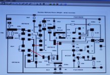
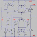
Hi Carlos, take it easy fella Honestly there really isn't a lot of a relationship between the circuit diagram i posted & a Pass amp. Only the operation of the output stage, but not the type of devices is similar. The front end is also totally different as you can see
The only common denominator is the way the output stage works, there will be no mosfets & no mosfet LTP driving a resistor. This front end has a current mirror & emitter follower with a current sink as a load, you really couldn't get much different.
By the way, this doesn't have to be biased right into class A operation. Though it'd be more linear with an amp or two (or more) of quiescent current the low frequency gain of the front end is a heck of a lot higher than a Mr Pass LTP using mosfets. Normally i'm not that keen on a lot of open loop gain, however i thought i'd give this a go as i just want to see how it performs as i prefer transitor outputs to mosfet.
Anyway, enough waffling
I guess my German sourced BC550C & BC560C transistors should be here this coming week (come on DHL). I know where the heatsinks are that i'll bolt the output transistors onto, though i haven't found the transistors yet
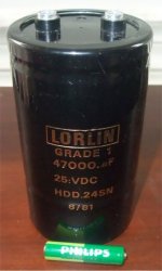
I have also found 6 of the 8 capacitors i'll need, though i think there might be 4 more or possibly & hopefully another 6 would be nice. As it is 100,000UF per rail should be ok. Nice big cans, can't beat them. NOS when i bought them back in the day, low & light usage. I guess i'd better reform them
Back soon, bests to all, Mark.
Honestly there really isn't a lot of a relationship between the circuit diagram i posted & a Pass amp. Only the operation of the output stage, but not the type of devices is similar. The front end is also totally different as you can see The only common denominator is the way the output stage works, there will be no mosfets & no mosfet LTP driving a resistor. This front end has a current mirror & emitter follower with a current sink as a load, you really couldn't get much different.
By the way, this doesn't have to be biased right into class A operation. Though it'd be more linear with an amp or two (or more) of quiescent current the low frequency gain of the front end is a heck of a lot higher than a Mr Pass LTP using mosfets. Normally i'm not that keen on a lot of open loop gain, however i thought i'd give this a go as i just want to see how it performs as i prefer transitor outputs to mosfet.
Anyway, enough waffling
I guess my German sourced BC550C & BC560C transistors should be here this coming week (come on DHL). I know where the heatsinks are that i'll bolt the output transistors onto, though i haven't found the transistors yet
I have also found 6 of the 8 capacitors i'll need, though i think there might be 4 more or possibly & hopefully another 6 would be nice. As it is 100,000UF per rail should be ok. Nice big cans, can't beat them. NOS when i bought them back in the day, low & light usage. I guess i'd better reform them
Back soon, bests to all, Mark.
Attachments
Well the transistors arrived from Germany today, so i can finally get down to a bit of breadboarding Very fast delivery & a far better price than i could find in the UK (about 2.4 pence each or 4c), then again a lot of stuff i bought for other projects came from USA as it was cheaper so what the heck I still need to locate the MJs though, i guess i'd better go on the hunt tomorrow.
Should have some kind of action going shortly
By the way Carlos, if you look in within a week or so i should have some interesting output stage topologies you can play about with..
Very fast delivery & a far better price than i could find in the UK (about 2.4 pence each or 4c), then again a lot of stuff i bought for other projects came from USA as it was cheaper so what the heck I still need to locate the MJs though, i guess i'd better go on the hunt tomorrow.Should have some kind of action going shortly
By the way Carlos, if you look in within a week or so i should have some interesting output stage topologies you can play about with..
Member
Joined 2009
Paid Member
No way Bigun...no way!.... only the day started to rain from the ground to the sky and the devil will be kissing Jesus.
Even NP in person asking i will not make any review or comparison about...made for myself only,
Carlos,
you make my laugh - you are the consumate entertainer on this forum ! - you underestimate your value to the forum, you attract a lot of visitors because you not only help people with DX corporation but also keep things lively.
Get a grip, take some Cachaça and tell us whether we want to build this amplifier - I have been working on an SRPP BJT design for the past few weeks (no LTP, one version with nfb and one without), I have a pcb design read to go but have put it on hold because of limited access to a chunky heatsink.
I think i will build the horizon next week schematic.
are there others?....have you post a schematic dear Bigun?
Cachaça is good..but next day, sometimes, a terrible headache comes that reduce your mood in a such way you may say to this girl, that wants you, not to bother you.
Go away dragon!...hic!
regards,
Carlos
are there others?....have you post a schematic dear Bigun?
Cachaça is good..but next day, sometimes, a terrible headache comes that reduce your mood in a such way you may say to this girl, that wants you, not to bother you.
Go away dragon!...hic!
regards,
Carlos
Attachments

Last edited:
Member
Joined 2009
Paid Member
are there others?....have you post a schematic dear Bigun?
Cachaça is good..but next day, sometimes, a terrible headache comes that reduce your mood in a such way you may say to this girl, that wants you, not to bother you.
Go away dragon!...hic!
regards,
Carlos
Now that would have to be some bad mood
Well I have quite a few schematics, from simple to more complex. I've posted below one of the simple ones because it's the basis for all the variants. The basic idea is a CFP stage on the bottom with SRPP on the top.
I like BJT instead of MOSFET and the CFP offers good linearity as well as increasing the input impedance. In Class A it never turns off so this helps with some of the stability concerns that taint this choice of topology.
This simple version has no error amplifier because I want to understand how it behaves without one. Adding a single PNP will give me an error amplifier fairly easily. In the meantime, lots of degeneration to keep gain under control. The pcb is a square shape, two bolt-through power devices and everything else on top allowing me to make the simple version and the variants. I haven't committed to making the pcb (at home of course) yet.
It's not too exciting to look at yet.
Attachments
Last edited:
What a change a day brings Nice to see some more posts on here & circuit diagrams & a rather attractive woman to say the least
I'm with Bigun when he says you are entertaining Carlos I always enjoy looking at your threads so you are most welcome on here
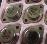
Well i'm scrapping the MJ11016 idea as i don't have a clue where they are, could be in the shed which is jam packed (16 x 8ft) or the greenhouse (i kid you not) So a very nice Englishman in the USA has just supplied me with a load of MJ11032 transistors which have a bigger SOA at these voltages & are 300W per device. Nice price to at $2.75 each + shipping. Cheapest i can find them in the UK is $7 lol.
Until they arrive i can mess about with some MJ11030, which at only 90V Vce are still usuable for testing purposes as they are rated at 2Amps @ 50V which is ok for messing about with. Same device as the 11032 just 90V instead of 120V.
I should have something cobbled together in a few days i'm hoping... Lets see.
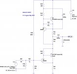
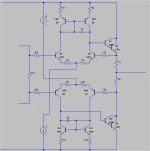
Well i said i'd post a few output stages. The first one is obviously an all N channel mosfet output stage. It took me an age to work out how to get a truly stable quiescent current combined with rail to rail voltage swing. The current is set via R27 which would be a simple variable resistor. As the mosfets are in a feedback loop the current should remain as stable as you like. The twin 12V supplies only need to supply about 1mA or less. They must match accurately & be totally seperate & floating. In fact it'd probably be easy enough to connect a constant current to each one from the +42V rail & use a shunt regulator like a TL431 to generate the 12V, again a 1mA constant current should be more than adequate. A small resistor connected directly accross the drain to source of the mosfet on the -30V rail will keep that 1mA current flowing if the mosfet is switched off (10K should do it) Match Q1 & 2, Q3 & 4, Q5 & 6, Q7 & 8 for best performance.
If you decided to use complimentary mosfets then simply mirror the top circuit on the -Ve voltage rail.
Second output stage uses Darlingtons. As we don't need to charge a mosfet gate to over 6V or more we don't need the 12V supplies. Again complimentary ouput devices could be used by changing the way things are wired.
Add your own front ends & Vas
Time for a beer
Bests, Mark.
Nice to see some more posts on here & circuit diagrams & a rather attractive woman to say the least I'm with Bigun when he says you are entertaining Carlos
I always enjoy looking at your threads so you are most welcome on here Well i'm scrapping the MJ11016 idea as i don't have a clue where they are, could be in the shed which is jam packed (16 x 8ft) or the greenhouse (i kid you not)
So a very nice Englishman in the USA has just supplied me with a load of MJ11032 transistors which have a bigger SOA at these voltages & are 300W per device. Nice price to at $2.75 each + shipping. Cheapest i can find them in the UK is $7 lol.Until they arrive i can mess about with some MJ11030, which at only 90V Vce are still usuable for testing purposes as they are rated at 2Amps @ 50V which is ok for messing about with. Same device as the 11032 just 90V instead of 120V.
I should have something cobbled together in a few days i'm hoping... Lets see.
Well i said i'd post a few output stages. The first one is obviously an all N channel mosfet output stage. It took me an age to work out how to get a truly stable quiescent current combined with rail to rail voltage swing. The current is set via R27 which would be a simple variable resistor. As the mosfets are in a feedback loop the current should remain as stable as you like. The twin 12V supplies only need to supply about 1mA or less. They must match accurately & be totally seperate & floating. In fact it'd probably be easy enough to connect a constant current to each one from the +42V rail & use a shunt regulator like a TL431 to generate the 12V, again a 1mA constant current should be more than adequate. A small resistor connected directly accross the drain to source of the mosfet on the -30V rail will keep that 1mA current flowing if the mosfet is switched off (10K should do it) Match Q1 & 2, Q3 & 4, Q5 & 6, Q7 & 8 for best performance.
If you decided to use complimentary mosfets then simply mirror the top circuit on the -Ve voltage rail.
Second output stage uses Darlingtons. As we don't need to charge a mosfet gate to over 6V or more we don't need the 12V supplies. Again complimentary ouput devices could be used by changing the way things are wired.
Add your own front ends & Vas
Time for a beer
Bests, Mark.
Attachments
I might be able to get on shortly
Been a while, my apologies My back has been playing up so my days have consisted of laying on my back & reading a book or two when not making dinner. Not much fun but it's improving steadily thankfully
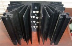
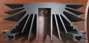
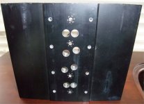
The postman brought me a nice little package from stateside this afternoon, so as i now have the proper transistors i dug out a couple of heatsinks that i'll use just to test the thing & get a basic feel of the relationships between the resistors & caps controlling the output stage. These heatsinks will be used on a different set of amps i'll be building in the future but they'll be fine for test purposes. Each is 0.5C/Watt so i'll still be able to operate at a reasonable bias current considering the +/- 24V supply. Thankfully they are pre drilled to accept TO3 devices
The plan is to still use 6 devices per amplifier & two amps to make a bridge, so the output stage will be a tad over rated considering the 100W 8ohm output i'm looking for. 3.6KW of transistors should be just about bomb proof along with some very simple current limiting, each transistor is rated to 50A continuous & pulse tested to 100A but they'll see nowhere near that ever. SOA of these is 3A @ 50V which is much better than the MJ11016.
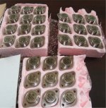
I bought 30 transistors so i could get some reasonable matches, they'll be matched in bunches of 3. I'm probably looking at running a 2Amp quiescent current through each amp so a total idle dissipation of approximately 200W for the complete bridge amp. I'll match the transistors Vbe at 0.666A.
Enough waffling for now, i'll be back with something when it's working
You can have some pics though...
Been a while, my apologies
My back has been playing up so my days have consisted of laying on my back & reading a book or two when not making dinner. Not much fun but it's improving steadily thankfully The postman brought me a nice little package from stateside this afternoon, so as i now have the proper transistors i dug out a couple of heatsinks that i'll use just to test the thing & get a basic feel of the relationships between the resistors & caps controlling the output stage. These heatsinks will be used on a different set of amps i'll be building in the future but they'll be fine for test purposes. Each is 0.5C/Watt so i'll still be able to operate at a reasonable bias current considering the +/- 24V supply. Thankfully they are pre drilled to accept TO3 devices
The plan is to still use 6 devices per amplifier & two amps to make a bridge, so the output stage will be a tad over rated considering the 100W 8ohm output i'm looking for. 3.6KW of transistors should be just about bomb proof along with some very simple current limiting, each transistor is rated to 50A continuous & pulse tested to 100A but they'll see nowhere near that ever. SOA of these is 3A @ 50V which is much better than the MJ11016.
I bought 30 transistors so i could get some reasonable matches, they'll be matched in bunches of 3. I'm probably looking at running a 2Amp quiescent current through each amp so a total idle dissipation of approximately 200W for the complete bridge amp. I'll match the transistors Vbe at 0.666A.
Enough waffling for now, i'll be back with something when it's working
You can have some pics though...
Attachments
Member
Joined 2009
Paid Member
looking good.
indeed.
i can feel that class a heat cooking already
mlloyd1
- Status
- This old topic is closed. If you want to reopen this topic, contact a moderator using the "Report Post" button.
- Home
- Amplifiers
- Solid State
- Has anyone implemented a Pass style power amp with bipolars?