Very good performance Sakis..the way Rodd Elliot use to say
This should have a good sound too ... by the waveforms ... observing them..seems a promise of good performance ... sometimes good waveforms gives a good indication of sound quality... sometimes, not always.
By your interest in this amplifier, seems this is the case.... once again...a simple amplifier with good looking waveforms... and may sound good, as you are skilled daily listening good brands...so..you know how to compare and has the needed tools and skills.
regards,
Carlos
Last edited:
Dear Current flow.... i think something was misunderstood about BD139/140
These transistors can face 100 volts from coletor to emitter
These transistors can operate above 100 Megahertz
The gain use to be from 90 to 220
Widely used, since the seventies...hundreds of factories used, now a days some designers still use them.... observe they are survivers, good and reliable within their limits of course.
More modern ones, alike Sakis has told us (BD829/830) can be better in dissipation (metal tab).... also can work in higher frequencies (higher Ft)....but observe have even smaller voltage from colector to emitter...and BD139/140 having a metalic tab alike the new ones have, can also dissipate 2 watts as i use them here..... i have build more than thousand amplifiers using it.... hundreds of brazilian factories still using them...when i was Radio Amateur (from 1970 to 2002) i used them to repair HF transceivers... the transistor worked as output drivers at 30 megahertz beating others transistors dedicated to Radio Frequency (2SC1971)...i have used in FM (98 to 108 Megahertz) transceivers and worked fine with very small losses compared to expensive units costing 12 times more!.
Designers still use them...even now a days.... people that has not prejudice because old (means tested, reliable) accept them because good ones.
I would like, my dear friends, to spend some time observing the datasheet...also observe the modern ones dear Sakis is introducing to us (2002 transistors... already old)...and do that in respect to thousands designers that have used and are still using...this way you gonna notice these designers are not stupid nor menthaly retarded..if they made that choice is because the transistor has good performance, as they have a brain inside the skull alike everyone of us.
regards,
Carlos
Attachments
Last edited:
Member
Joined 2009
Paid Member
i wasnt expecting a noticable diference but even though the bias is quiet low since size of the box and heatsink i didnt want to create high temperature inside still it plays by far better than the 139-140 or 15030-31
can anyone explain why ????
can any one double check this and provide an opinion ???
thanks sakis
You have a new baby - this might make all things more wonderful than they were before !
One difference you made was the bias. Before you had 120mA and now you have only 30mA. Perhaps it is now optimally biassed and before it was not. If you reduce bias in the bigger amplifier to the same level do you perceive a difference ?
An explanation about depends the evaluator's goodwill
If the evaluator like you, then he will think you have "tuned" your amplifier to an optimized setting.... and reduced the power consumption creating a green amplifiers.
If the evaluator does not like you, and want to burn your amplifier image, also your personnal image, then he will say the reduction of bias is dangerous, because will make the ouput transistors work very near the crossover region area, and this may drive them to produce crossover noises while changing state of conduction to non conduction.
So, you see that the same reality can be evaluated, and view, from 2 or more point of views
As i believe in Sakis.... mine evaluation is the first one.... and i will test these transistors he said are excelent.
regards,
Carlos
You have a new baby - this might make all things more wonderful than they were before !
One difference you made was the bias. Before you had 120mA and now you have only 30mA. Perhaps it is now optimally biassed and before it was not. If you reduce bias in the bigger amplifier to the same level do you perceive a difference ?
thanks for your wishes about our new baby ... but the P3a as was with all the small mods presented in the thread is standing on my bench almost 3 years now .....it is my standard listening system for the times i am in my shop normally from 9.00 till 21.00 and i listen from the same sources all the time and for testing perpus always the same music
now 3 years is a lot of time to listen to this amp also in the past three years i have bulited almost 20 of these amps while trying new pcb versions making other style of cooling but never tested so far with these drivers
in between in these three years i repaired about 250 amplifiers or more so standard procedure is to listen to them compaired to the P3A as is
so belive me i know this amlifier by far very well .....
These transistors can face 100 volts from coletor to emitter
These transistors can operate above 100 Megahertz
The gain use to be from 90 to 220
Carlos
Hi Carlos,
You're absolutely right for the transition frequency. It appears that the datasheet origin for the BD139 I quoted was unreliable. Many manufacturers don't quote this parameter, with the exception of Philips and Siemens.
I have no doubt that the BD139/140 pair are good performers in audio applications, although you may now be tempted to try the BD829/830 in your DX Blame ES to see if the effect is as marked as Sakis found in his P3A
")
Regards,
Steve
you may now be tempted to try the BD829/830 in your DX Blame ES to see if the effect is as marked as Sakis found in his P3A
Im ready
But from what I have heard/read about Dx, and now here the close looking P3a, we may need the opposite of what Sakis has achieved with P3a
Dont know if that makes sense
Sakis, I hope you dont mind me showing my layout version of Dx, just to show where I would like to take it
Attachments
to be honest with you ...no i dont mind at all but i also dont understand what oposite means ...
also i cannot understand much of your pcb or your "version" of DX
also to put things in a proper track i have no expirence with your schematic or P3A versions that drive multiple outs in such a low rail voltage ....
probably what you present is moded circuit of something else ...
kind regards sakis
( tinitus .... i can also sent you a proper pcb software for free if you want i have sprint layout 4 that i dont use any more since i have version 5 i will be more than happy to mail you a cd fo free ...probably it can make your pcb more undersatndable )
Last edited:
I will try these transistors... Sakis is mailing some to me..also i will search for
them in São Paulo....yes.... i will do it current flow...he said sound i better...i want listen that as i have tested several and no one sounded better in the VAS position... no MJE340/350, nor 2SC4793 and no MJE150128 and also tried MJE15032... some others was tried too... he perceived advantage..so.. i am interested to know that too.... he does things building and listening...so..real world effect is what i want.
Sakis is Dx Corporation of Greece...old friend that has built some nice amplifiers.... skilled...use to fix amplifier and to build amplifier for customers, Bars and Restaurants.
He is the one can answer questions and can decide things about Dx Corporation in Greece... an authorized dealer.
regards,
Carlos
Last edited:
Im ready
But from what I have heard/read about Dx, and now here the close looking P3a, we may need the opposite of what Sakis has achieved with P3a
Dont know if that makes sense
Not quite!
I will try these transistors... Sakis is mailing some to me..also i will search for them in São Paulo....yes.... i will do it current flow...he said sound i better...i want listen that as i have tested several and no one sounded better in the VAS position...
I look forward to your findings.
Regards,
Steve
P3A is a different amplifier...alike has bootstrap...but differential current is
different (higher)...the VAS current is different (lower)..the output sounds different because it is another type... the decision about input input capacitor is very different... the decision taken about the Miller is also different..another philosophy, another idea, that has its own advantages and disadvantages.... worries about waveform and distortion above the human audibility limits is also different..seems he does not worry about things we cannot listen..he is rigth once again.
It sounds good...i have built it several years ago and now i have measured in the simulator.
Performance measured is different when compared to the Dx Amplifier, as an example ....another bootstrapped amplifier....listening it is also very different....but in the scope if performs even better than the Dx amplifier...simulator is a little bit worse..but difference is below human capacities to detect.... say, one amplifier having 0.023% THD and other having 0.048% THD.
So, Rodd, as usual, is rigth.... very simple and having very good performance..not to be underestimated.
Our masters, our teachers, these men... Rodd, Hugh, Nelson Pass, Douglas Self, Slone, Duncan, JLH and others are the ones we should respect and try their designs.
In my simulator schematic, the CCS control of current, the resistance, was reduced to obtain 300uV off set instead of 41 milivolts (not bad too..this means nothing...small power)...the bias resistance, the one should be adjusted, a variable 2K trimpot...was adjusted to obtain 100mA each rail... interesting..the amplifier does not accept tweaks in the Miller capacitor..the value should be the one Rodd has pointed us.
regards,
Carlos
Attachments
Last edited:
to be honest with you ...no i dont mind at all but i also dont understand what oposite means ...
...........
probably what you present is moded circuit of something else ...
kind regards sakis
( tinitus .... i can also sent you a proper pcb software for free if you want i have sprint layout 4 that i dont use any more since i have version 5 i will be more than happy to mail you a cd fo free ...probably it can make your pcb more undersatndable )
Thanks Sakis
I would like to try a software
Not that I need it much
But if I cant use it I could always pass it on to another member
Have tried another software suggested to me, and I couldnt make it work
So it may be wasted on me
Frontend and driver layout I have shown is 100% straight Dx, no changes so far...unless I have made mistakes
Mainly I do it to learn, and to put me in a position where I can at least hardwire output stage
A year ago I would have had no idea about it
I can see my post was confusing, with regards to saying that P3a and Dx maybe needing pushed in opposite direction to each other
1. I understand from Carlos as if Dx may be a bit on the soft side, which I interprit it as maybe being a bit grainy
2. I dont know P3a, but it sounds like you are saying you have pushed it in the direction of sounding softer, nicer
All in all, that indicates to me like P3a and Dx start out at opposite ends, regarding their sound nature
But I know all to well to NOT say stuff like that, considering having not heard any of them
But then, isnt that what describing sound is supposed to be good fore
So, how is the sound nature of P3a, before you modded it ?
So, how is the sound nature of P3a, before you modded it ?
through the 3 years i ve been working arround from time to time with this amplifier starting with the first one that has been produced since day one it was made to rock from scratch in the pcb every litle detail was taken care of , and the material used was the best available nothing exotic this version was simply close to perfect
for fun i constructed some version with wrong pcb and low quality material that actually played bellow average
from all this time only a few days ago i ve seen that the 829-830 drivers made a serious audible diference as described above ...
beyond that i have never heard how this is working with Rods pcb and construction rules
for reference i will say once more that the construction i made is based on P3A schematic but features a couple of things like
matched ltp pair with thermal junction
silver mica, filter and miller,
multileyer driver miller cap ,
vbe attached to one of the driver
4 x 0.68 ohm output resistor ( results 10W 0.33 ) per tranistor
no inductor
2X10.000 mfd on board
and always except once 2sa1302 3281 original toshibas for the out
fairchild 1943+5200 sounded more muffy
so true comparsion with the original make of the P3A was never done ( hell it might as well play better than mine )
other than the above the P3A i make sounds as described in the first post
thanks for your time and interest
kind regards sakis
Last edited:
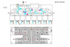
service akai am75
SERVICE AKAI AM 75
AKAI AM 75 visited my shop for repair seriously canibalized from a costumer that wanted to practice his repair skills ( very explosive !!! )
quiet a hard job to do since this amplifier features
1 gozillion curent surces
1 gozillion diferent rail voltage per division
modular style of construction
1 gozillion of wiring for almost everything ....
I wonder what the designer had in mind ???? never seen a so complicated machine with almost no reason ... ( for only 100+ watts at class AB and 65 ma of bias )
In a few words there is one board the is short of first stage and phono EQ and ofset controls
then there is another one that is called voltage amplifier and has every possible technology or any available techonlogy at the time and uses transitors fets current mirrors and current sources ( with also all the set up for line inputs on it )
then there is piggy board for the bias
now on the "mother board" is the main power supply ...Vi limmiters ... and another triple secondary power supply fully curent mirrored and stabilized with nine ( 9!!!! ) output transistors to regulate various voltages needed here and there ...
interwiring all these boards is a complete mess since to be able to fit all that in a 3U box was a pain in the @ss resulting all types of cables mixed and tied up all around
add to all the above that amplifier needs tone controls muting circuits and selector board all together with a digital input board ( !!! ) and your spaggheti is ready
never seen a japanese machine constructed in such a mess ( probably the designer was European ha ha ha ha )
got it repaired with all shorts of problems ( secondary psu, drivers and outputs blown to mars due to thermal stress and terible soldering)
and didnt even bother to listen to it
any body has a couple of years to spent to study the schematic ( that actually has a few mistakes ) i will be more than happy to provide
sorry i dindnt like it ... no photos no listenig comments
Last edited:
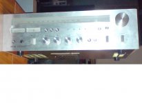
service AKAI AA 1050
A terrible machine ....compaired to todays standarts its a complete cr@@p
no serious damages a classic story ...all capacitors dead and replaced all pots and switches cleaned very carefully ( any day i will uprise a thread about contact cleaning with a new product i invented that seems to rock but still in testing mode ) ...a few lamps also replaced tuned...biassed ...idled it and go
enough power above 50 clean watts wonderful semis inside terrible crosstalk figures even though the selector switch is a mastepiece of engineering at the times signal rooting was terrible so everything jumps from here to there .... an average tuner with good sensitivity but not that good sound ...
Question why ???
why people spent money on machins like that ??? only a few things one that its nice to keep alive ...a unit like that will never be produced again in the feature... and then if you skip quality mambo jambo for a minute the sound that comes from this machine has unbeatable colorations that of course are not real or correct but very dear to listen ...
let us not forget that this machine has a very good chance to outperform me since its expeted to live another 30 years ...at least ..
regards sakis
Attachments
- Home
- Amplifiers
- Solid State
- P3A Comparison table ( long .... )