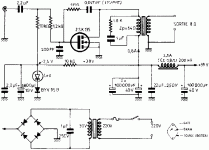
On the schematic they have it looks like a bias point of 2.45volts. The current going to the OPT is 0.8 amps.
Looking at old datasheets for the 2SK135 this cannot be possible.
What is the actual bias and quiscent current for the amp???
Thanks.
p.s. I want to use the BUZ900P series instead.... what should I change?
Looking at old datasheets for the 2SK135 this cannot be possible.
What is the actual bias and quiscent current for the amp???
Thanks.
p.s. I want to use the BUZ900P series instead.... what should I change?
Attachments
If you just look at the spec sheet the bias looks high.
But the RDS goes up from 1R0 to 1R7 over temperaure.
This is enough to require a higher gate voltage to keep the current in the ball park.
Running 30W through a 100W part is smokin' hot, I'll let you calculate the junction temperature.
But the RDS goes up from 1R0 to 1R7 over temperaure.
This is enough to require a higher gate voltage to keep the current in the ball park.
Running 30W through a 100W part is smokin' hot, I'll let you calculate the junction temperature.
No more suggestions???
Come on.... there has to be someone else out there with suggestions about this circuit.
Planning on using 68,000uf of capacitance (or maybe 136Kuf) and battery supply.
Have some coupling caps... use Riken Ohm wherever I can.
EP OPT.
etc....
Can anyone explain the bias issue yet???
Thanks!
Come on.... there has to be someone else out there with suggestions about this circuit.
Planning on using 68,000uf of capacitance (or maybe 136Kuf) and battery supply.
Have some coupling caps... use Riken Ohm wherever I can.
EP OPT.
etc....
Can anyone explain the bias issue yet???
Thanks!
what is the purpose behind the resistor and cap across the primary of the opt?
Is a zobel network...for limiting the high frequencyes and making the primary of the tranformer look less inductif to the mos- fet.
and the purpose of the resistor and cap from drain to gate?
Is to introduce some AC feedback and limit the distortion...that even so will be high...
question on 1M feedback resistor.
In the design there is a RC combo using a 1M resistor and a cap to the gate.
How does this local feedback affect biasing??
Also, If I were to take out the cap input and just have a 2:1 input transformer.. how would I bias the mosfet and would I adjust the 1M resistor??
Haven't decided on what mosfet to use yet... something with low gate capacitance.
Thanks!!!
- Status
- This old topic is closed. If you want to reopen this topic, contact a moderator using the "Report Post" button.
- Home
- Amplifiers
- Solid State
- Help on Nemesis amp
