Happy new year to all Fellas here.
Only one little question about CA-9.
I was searching from post 12.04.2020 when Mr. Miles has showen a nice
build and layout, 100 sides now.
Have i missed some gerbers from layout?
Is it possible that to share here, otherwise i will work on own, close to this, layout.
Regards.
Only one little question about CA-9.
I was searching from post 12.04.2020 when Mr. Miles has showen a nice
build and layout, 100 sides now.
Have i missed some gerbers from layout?
Is it possible that to share here, otherwise i will work on own, close to this, layout.
Regards.
Hi,yes. i made a mistake at MM-MC phono preamplifier,so later i will post corrected files. i have also decreased current of a-class shunt to achive less heating in inclosure by increasing 22r to 47r (for pair of phono) and to 62r (for preamp with tone controle). i have put 22k at input of preaplifier with tone controle and a switch with 18k in parallel with that 22k to achive amlifying ratio of 1 and 2,2. it is not necessary but that is what i wanted.
YouTube
Do you have MM / MC phono preamp gerber file.
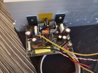
Hi everyone
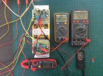
I made 4 Active servo PSU with LM317 and all of them works.
But, I have fluctuation in output voltage on second decimal.
I got 15.09 and 15.10V. It changes in time every few seconds.
That means at least 50mV gap.
I built this, because I think that is more stable then LM317. I was thought that servo is for better ripple rejection.
After some digging on net I found, that this servo is for rejection of HF noise.
NE5532 here act as voltage comparator. Plus is on ground, and minus is also on 0 volts because it is linked via 10uF to output voltage.
If on output we got some AC signal it pass over 10uF and 1K resistor and the difference voltage is amplified via IC and pass into adj of LM317.
Here I am lot of questions.
If this is servo, why we amplify the difference signal ?
With 33K/1K we have amplification of 33 times. If we pass this to adj pin we make another difference 32 times greater.
I think that there must be combination of 33K/33k or 10K/10K for unity gain. Diferrence signal then be oposite sign, same intensity and theoretically on output of supply we got original voltage without noise.
Second question is why 33p and why 10uF.
33K/33p is filter which don't pass frequencies above 50Khz
10K/33p is filter which don't pass frequencies above 100Khz
33K/3.3p is filter which don't pass frequencies above 110Khz
10K/10uF pass from 10Hz
1K/1uF pass from near 1Khz
1K/10uF pass form near 100Hz
10K/1uf pass from near 100hz
If we wish eliminate noise from line, or all what come from load, why only HF ?
I think it must be all frequencies.
With 10K/33p in feedback and 10K/10uF on minus input we have unity gain and passing frequencies from 10Hz to 100Khz via opamp to adj pin of LM317.
I tried different combinations, 33K/33p with 1K/10uf, with 10K/10uF and with 33K/10uf on input, and at end 10K/33p and 10K/10uF and got always same result. Voltage 15.09 and 15.10 which is not stable.
I was measured with 3 voltmeters, and in one put new duraccell batteries.
I noticed some small HF noise in speakers, which should not be there with this circuit.
I had problems on 2 of them, and solved with Ne5532 +/-Vcc decoupling with 22R/10u as on schematic.
I put low ESR capacitors for 10uF capacitors and out capacitor . All of capacitors have 100n bypass capacitors.
I don't have oscilloscope to see is there oscillations or not.
My load is about 60mA.
In spice simulation all works fine, i put voltage generator 3V/8000Hz on load, an got ripple near 0.15mA.
Have the protect diodes or low ESR capacitors some influence ?
Have someone idea why the output voltage is not completely stable ?
Attachments
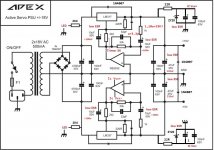
APEX VU8S
Hello,
For those who are interested, I extracted the electrical diagram of the VU8S vu-meter.
An error occurred in the APEX VU12S wiring presented by apexaudio, namely the AO LM339 inputs were reversed.
The correct connections are shown in the attached diagram.
Thanks apexaudio for the tips.
All the best.")
Hello,
For those who are interested, I extracted the electrical diagram of the VU8S vu-meter.
An error occurred in the APEX VU12S wiring presented by apexaudio, namely the AO LM339 inputs were reversed.
The correct connections are shown in the attached diagram.
Thanks apexaudio for the tips.
All the best.
Attachments
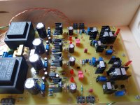
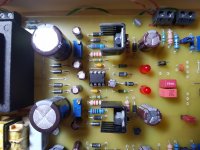
Since didn't get any response from Experts in the Group I decided to print, etch drill and make Sara and 2 more projects.Alpha Darlington 5 pairs out , one channel completed and tested, So it is now make and test.
SARA-2016
If you need help ask me anytime. Best regards, RaimondAudio.
Friends I have cloned SARA Amp , P.c.b. designed by Alex MM.revised version 5 , 2017.Changes I have made are because of the availability of the components on my end , Experts please check.
Hi,
You haven't got a reply probably for this is not SARA's thread....
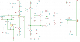
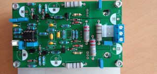
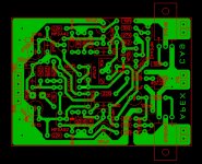
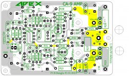
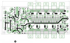
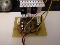
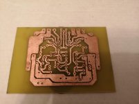
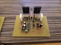
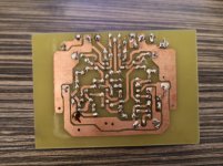
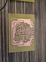
CA9 Amp Board
Hello again
i have done a bit homework and put a little board.
Hope it works.
Please take a look to correct contacted traces.
Inspired by following posted schematic, pic and layout
i came up to this one.
If it is OK i will share gerbers as next.
And mostly cloned Prasi's AA9MD board without fuses.
Thanks for sharing Prasi.
Best Regards.
Attachments
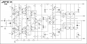
Apex AX11 Bimo mod problem
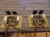
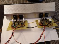
Hi guys, I have tried to reactivate my diy activities this winter and I have chosen Apex AX11 Bimo mod as a project.
Home etched pcbs and did one channel, it sings but I cant adjust bias, there is no voltage on 2sc5200's emiter resistor 0.22r (0V), on 2sc1943's there is 12mV voltage drop. No reaction to trimer (used 1k trimer).
Since then, I changed all actives and checked all passives and couldnt identify the problem.
Has anyone made this build succesefully by layout in attachment?
I checked pcb traces and they seem ok, same as in pdf.
Any ideas?
(Another problem is a little noise in highs, not much but like constant wind in tree's canopy, maybe it is a nusproduct of defunct bias setup?)
Thanks!
Hi guys, I have tried to reactivate my diy activities this winter
and I have chosen Apex AX11 Bimo mod as a project. Home etched pcbs and did one channel, it sings but I cant adjust bias, there is no voltage on 2sc5200's emiter resistor 0.22r (0V), on 2sc1943's there is 12mV voltage drop. No reaction to trimer (used 1k trimer).
Since then, I changed all actives and checked all passives and couldnt identify the problem.
Has anyone made this build succesefully by layout in attachment?
I checked pcb traces and they seem ok, same as in pdf.
Any ideas?
(Another problem is a little noise in highs, not much but like constant wind in tree's canopy
, maybe it is a nusproduct of defunct bias setup?)Thanks!
Attachments
Sorry about that. That is why I wrote check for accuracy. Here is an edited version.
Have you or anyone else made a Sprint Lay6 file of this or posted gerbers?
Thank you,
David.
Have you or anyone else made a Sprint Lay6 file of this or posted gerbers?
Thank you,
David.
Can you give the post number so I know what you are referring to? I probably have the Sprint file.
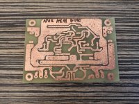
solved
I have just solved a problem with my build , it was inverted bd139. AX11 Bimo mod now works fine. In the meantime, I built AX11 vanilla and it works like a charm. Now I have 2 versions of AX11 to compare with.
I have just solved a problem with my build , it was inverted bd139
. AX11 Bimo mod now works fine. In the meantime, I built AX11 vanilla and it works like a charm. Now I have 2 versions of AX11 to compare with. Attachments
Last edited:
Can you give the post number so I know what you are referring to? I probably have the Sprint file.
This post,
https://www.diyaudio.com/forums/sol...mate-fidelity-amplifier-1121.html#post5799206
Unless you have a more current Sprint version of the Apex speaker protect.
Do you also have a Sprint version of the Apex Start/Stop?
Thank you,
David.
This post,
https://www.diyaudio.com/forums/sol...mate-fidelity-amplifier-1121.html#post5799206
Unless you have a more current Sprint version of the Apex speaker protect.
Do you also have a Sprint version of the Apex Start/Stop?
Thank you,
David.
The link just takes me to the top of the page. I need the post number.
The link just takes me to the top of the page. I need the post number.
Post #11210.
FH11 with modifications suggested by Mr. Miles.
@XRK, could you update schematic with modifications.
@Bangla H, I use sprint layout easy to use but more likely I make mistake while drawing layout. But it's fun once you get hang of it.
I started with eagle and still use it for digital layout.
you have Layout? Can I make it?
- Home
- Amplifiers
- Solid State
- 100W Ultimate Fidelity Amplifier