thank you apexaudio
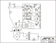
psu have dc protect too?
Yes
still no audio coming out just strong hum.
bias 0,6mV
out Vdc -9,2mV (when in and sgnd short)
out Vdc 7,6mV to 11mV changing (when in and sgnd separate and in is not connected any where)
45-0-45 Vdc rail voltage.
nothing change when i remove the 10R from sgnd to gnd.
i will come back with more mesurements. if any compenent need to be known mesurement please let me know for losing time for mesure other components.
Attachments
i cant find where is the problem 
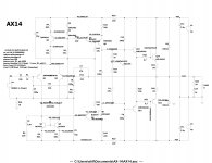
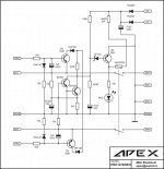
here all transistors mesurement;
Q1 2N5401
VBE 0,6mV
VBC 1,2mV
VCE 1,2mV
Q2 2N5401
VEB 0,5mV
VBC 0,2mV
VCE 1mV
Q3 2N5401
VBE 0,4mV
VBC 0,9mV
VCE 1mV
Q4 BC547
VBE 0,5mV
VBC 0,5mV
VCE 1,2mV
Q5 BC547
VBE 0,3mV
VBC 0,3mV
VCE 0,3mV
Q6 BC557
VBE 0,8mV
VBC 0,8mV
VCE 0,8mV
Q7 2N5551
VBE 0,6mV
VBC 0,6mV
VCE 0,6mV
Q8 MJE340
VBE 0,6V
VBC 39,6V
VCE 41,8V
Q9 MJE350
VBE 0,6V
VBC 39,7V
VCE 38,9V
Q10 BD139
VBE 0,6V
VBC 1,6V
VCE 2,2V
Q11 2SA1837
VBE 0,6V
VBC 42,9V
VCE 43,5V
Q12 2SA1943
VBE 0,5V
VBC 43,6V
VCE 44,1V
Q13 2SC4793
VBE 0,6V
VBC 43V
VCE 43,6V
Q14 2SC5200
VBE 0,5V
VBC 43,7V
VCE 44,3V
i cant find where is the problem
here all transistors mesurement;
Q1 2N5401
VBE 0,6mV
VBC 1,2mV
VCE 1,2mV
Q2 2N5401
VEB 0,5mV
VBC 0,2mV
VCE 1mV
Q3 2N5401
VBE 0,4mV
VBC 0,9mV
VCE 1mV
Q4 BC547
VBE 0,5mV
VBC 0,5mV
VCE 1,2mV
Q5 BC547
VBE 0,3mV
VBC 0,3mV
VCE 0,3mV
Q6 BC557
VBE 0,8mV
VBC 0,8mV
VCE 0,8mV
Q7 2N5551
VBE 0,6mV
VBC 0,6mV
VCE 0,6mV
Q8 MJE340
VBE 0,6V
VBC 39,6V
VCE 41,8V
Q9 MJE350
VBE 0,6V
VBC 39,7V
VCE 38,9V
Q10 BD139
VBE 0,6V
VBC 1,6V
VCE 2,2V
Q11 2SA1837
VBE 0,6V
VBC 42,9V
VCE 43,5V
Q12 2SA1943
VBE 0,5V
VBC 43,6V
VCE 44,1V
Q13 2SC4793
VBE 0,6V
VBC 43V
VCE 43,6V
Q14 2SC5200
VBE 0,5V
VBC 43,7V
VCE 44,3V
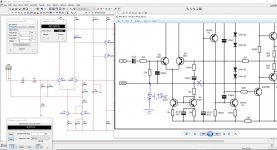
These measurements make no sense. The whole front end is off. VCE of Q3 should be around 32V. VCE of Q1 and Q2 should be around 41-42V
still no audio coming out just strong hum.
bias 0,6mV
out Vdc -9,2mV (when in and sgnd short)
out Vdc 7,6mV to 11mV changing (when in and sgnd separate and in is not connected any where)
45-0-45 Vdc rail voltage.
nothing change when i remove the 10R from sgnd to gnd.
i will come back with more mesurements. if any compenent need to be known mesurement please let me know for losing time for mesure other components.
Bias too low ? 0.6mv=1.8ma
Look at these.
ty for answer, this cn be happen cause of the wrong bias setting?
Bias too low ? 0.6mv=1.8ma
thank you, i think i read set that 0.33ohm 5w resistors 0,5mv. i am going to check again but now i see apexaudio write in here somewhere take out fuses and put 10R and set 1V on them. i just see his this write.
i am confused and trying to learn. BIAS not setting on 5w resistors which ones connected on the emiter of the power transistors?
which one is right A or B ?
Attachments
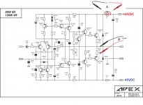
It's the samething, measure over 10e gives you a total current. Measure over 0.33e 5w gives you current through output TR. Most of the current flows through output TR anyway. For ax14 I set v over 0.33e 5w to be 30mv.
hi ty for your explane. before i read your write i change the bias on 5w resistor up to 2mv. now its working realy clear bass and mids but high freq. are i think broking. i will try now 30mv.
another thing is if i disconnec audio signal. then the problems coming out. big humm coming. i will try 30mv and come back thank you again
i left it open witouth signal it get warm..
i checkthi bias on 5w resistors its rising and when it warm now its 28,3mV
out voltage is -16,6mV
there is some thing i see if i open volume up (i cannot open now cause of my sister babies sleeping. quality of sound is broking bass going more soft and mids coming front side. i think why apexaudio make a tone preamp build behind amplifier.
sory for bad english and thank you soo much for your helps. i hope i can fix that 2 mistakes too. i will put pictures when i finish psu and put in chase all together.
The bias should be set to around 25-30mA on the AX-14.
V = IxR = 0.03 x 0.33 = ~10mV across the 0.33R resistor.
30mV is giving you closer to 90mA bias which IMO is too much.
Also, DC at the output <50mV is usually fine.
ty for answer i will try 10mV to day
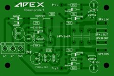
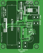
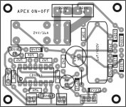
Hello, what changes should be made to use 45 0 45 VAC in this protection?
560R\2W replace with 1k2\5W
Attachments
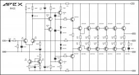
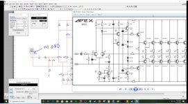
hello guys I made the simulation of the Apex BX22 and I notice something weird if I connect those components as GND I lost power but if I disconnect them it will amplified normally or maybe is my simulation that is wrong I'm confuse? I fallow the schematic as accurate as possible for testing I add that R34 4R7 only for testing is not part of the original schematic
Attachments
- Home
- Amplifiers
- Solid State
- 100W Ultimate Fidelity Amplifier