


I also had problem with bias until I had MJE15034-35 as drivers. when I replaced them with 2SA\2SC drivers as in schematic I had no bias problem.
I use mje15030 / 31 for current drivers
Hello , I have a problem .Starting ax14 with a constant voltage of 31v . the lamp is not lit in the circuit of 220v . Connected SGND to the ground of the power supply nothing has changed. The second channel is full short, the bulb in the 220v network is lit constantly and brightly. ask for help. Thanks
<a target="_blank" href="https://d.radikal.ru/d27/1907/8c/8afbf4057d9b.jpg"><img src="https://d.radikal.ru/d27/1907/8c/8afbf4057d9bt.jpg" /></a>
<a target="_blank" href="https://b.radikal.ru/b16/1907/01/a0ceca646d02.jpg"><img src="https://b.radikal.ru/b16/1907/01/a0ceca646d02t.jpg" /></a>
<a target="_blank" href="https://b.radikal.ru/b35/1907/66/d5ac89a11e6f.jpg"><img src="https://b.radikal.ru/b35/1907/66/d5ac89a11e6ft.jpg" /></a>
Hello , I have a problem .Starting ax14 with a constant voltage of 31v . the lamp is not lit in the circuit of 220v . Connected SGND to the ground of the power supply nothing has changed. The second channel is full short, the bulb in the 220v network is lit constantly and brightly. ask for help. Thanks
Still building.....AX14. I'm chipping away a little bit everyday. Making changes here and there.
Just read further back in the thread to dump the 50v 100pf ceramic caps. Must be at least 100v. So will probably put a couple more micas in tomorrow. Still waiting on my C6 100uf 16v caps to arrive. I have a Transistor matcher being sent to me from a friend. Then I can go through and see what I've got matched. Also waiting on my 0.33r resistors err. I also have some nice fuse holders coming but might go the naked single clip end versions. What size Heatsinks is everyone using? Conrad Heatsinks isn't to far away from me. Might just go the 350mm x 152mm x 50mm that I have for my Pass AlephMini amp.


Just read further back in the thread to dump the 50v 100pf ceramic caps. Must be at least 100v. So will probably put a couple more micas in tomorrow. Still waiting on my C6 100uf 16v caps to arrive. I have a Transistor matcher being sent to me from a friend. Then I can go through and see what I've got matched. Also waiting on my 0.33r resistors err. I also have some nice fuse holders coming but might go the naked single clip end versions. What size Heatsinks is everyone using? Conrad Heatsinks isn't to far away from me. Might just go the 350mm x 152mm x 50mm that I have for my Pass AlephMini amp.
My 800va toroidal arrived. I will be using it with the Honey Badger I'm building but will also use this same toroidal for the A40 I build down the track.
I'm still waiting on parts for my AX14. I have a 300va 25v-0-25v toroidal for it will this be fine? What optimal for the AX14 Prasi Version. Thanks


I'm still waiting on parts for my AX14. I have a 300va 25v-0-25v toroidal for it will this be fine? What optimal for the AX14 Prasi Version. Thanks
I wanted to come full circle - I made 5 channels of the dual output FH11 (from EagleMod's v1.07) and due my stupidity 1 channel let out the Magic Smoke.
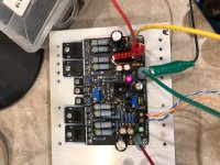
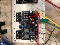
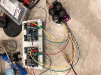
I'm posting a few (very poor) pictures of the still in progress build. Let me know if you have suggestions or comments.
PSU - ~68V unloaded, ~65 with a load, with 100V/40,000uF caps (PSU in pic was for initial testing at +/-40V).
Heatsink is 10-1/2" x 5" with 1" fins and a 3/8" base. 2 channels on each HS
4U case with full vented both and top
I have played loud music and a 1k sine wave for over an hour with both channels playing, and the fins stay at ~45C and I can easily put my hand on it for 5-10 seconds without discomfort.
It will be inside an enclosure, so no hands will be able to touch it even it reaches 60C+ so I don't think I will be a problem. I have had two hard weeks of testing all 4 channels inside the case, without a problem.
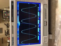
The last picture is my Oscope results just barely into clipping (no load) don't have a big enough dummy load for a 8/4r try (only have 100 watts). If my math is correct 121V is ~199 watts - right as clipping occurs.
I just got the Oscope, so this was my first try, so let me know if you see errors in my methods. I just monitored input on Channel 1 (not shown in pic) and output on channel 2 and turned up the input until I saw clipping (121V) on the output, using a 1k sine wave at 0db from my iphone app.
Thanks to APEX, xrk971, prasi, eaglemod - I would say this is a beginner amp because of all your hardwork, it really is order, populate and power-up. Just make sure you turn the bias pot completely counter-clock-wise before powering up (don't ask me how I know) and use a DBT, you can make this amp your first try without any issues.
I'm posting a few (very poor) pictures of the still in progress build. Let me know if you have suggestions or comments.
PSU - ~68V unloaded, ~65 with a load, with 100V/40,000uF caps (PSU in pic was for initial testing at +/-40V).
Heatsink is 10-1/2" x 5" with 1" fins and a 3/8" base. 2 channels on each HS
4U case with full vented both and top
I have played loud music and a 1k sine wave for over an hour with both channels playing, and the fins stay at ~45C and I can easily put my hand on it for 5-10 seconds without discomfort.
It will be inside an enclosure, so no hands will be able to touch it even it reaches 60C+ so I don't think I will be a problem. I have had two hard weeks of testing all 4 channels inside the case, without a problem.
The last picture is my Oscope results just barely into clipping (no load) don't have a big enough dummy load for a 8/4r try (only have 100 watts). If my math is correct 121V is ~199 watts - right as clipping occurs.
I just got the Oscope, so this was my first try, so let me know if you see errors in my methods. I just monitored input on Channel 1 (not shown in pic) and output on channel 2 and turned up the input until I saw clipping (121V) on the output, using a 1k sine wave at 0db from my iphone app.
Thanks to APEX, xrk971, prasi, eaglemod - I would say this is a beginner amp because of all your hardwork, it really is order, populate and power-up. Just make sure you turn the bias pot completely counter-clock-wise before powering up (don't ask me how I know) and use a DBT, you can make this amp your first try without any issues.
Attachments
-
 Oscope.jpg121.1 KB · Views: 295
 -
 FH11-HV-V1.07.JPG130.5 KB · Views: 379
 -
 FH11V1.0.7view.JPG383.2 KB · Views: 336
 -
 Right on heatsink.jpg115.4 KB · Views: 740
 -
 Left on heatsink.jpg117.8 KB · Views: 704
 -
 pair on heatsink.jpg136 KB · Views: 715
 -
 partial2.jpg137 KB · Views: 729
 -
 partial.jpg111.4 KB · Views: 727
My 800va toroidal arrived. I will be using it with the Honey Badger I'm building but will also use this same toroidal for the A40 I build down the track.
I'm still waiting on parts for my AX14. I have a 300va 25v-0-25v toroidal for it will this be fine? What optimal for the AX14 Prasi Version. Thanks
300VA with 35V-0-35V will be fine with 8 ohm load stereo.
Also input RC filter cap will be fine with 50V.
Only those which fit across b-c of drivers and across feedback resistor need to be higher voltage.
If you find silver mica's difficult or costly to procure, use NPO/C0G 100-200V rated ones.
All the best for your build. If you need any more clarification let me know, I will try and help.
regards
Prasi
With no load on the output you can't measure the RMS output wattage because the resistance portion of the equation is missing.I wanted to come full circle - I made 5 channels of the dual output FH11 (from EagleMod's v1.07) and due my stupidity 1 channel let out the Magic Smoke.
I'm posting a few (very poor) pictures of the still in progress build. Let me know if you have suggestions or comments.
PSU - ~68V unloaded, ~65 with a load, with 100V/40,000uF caps (PSU in pic was for initial testing at +/-40V).
Heatsink is 10-1/2" x 5" with 1" fins and a 3/8" base. 2 channels on each HS
4U case with full vented both and top
I have played loud music and a 1k sine wave for over an hour with both channels playing, and the fins stay at ~45C and I can easily put my hand on it for 5-10 seconds without discomfort.
It will be inside an enclosure, so no hands will be able to touch it even it reaches 60C+ so I don't think I will be a problem. I have had two hard weeks of testing all 4 channels inside the case, without a problem.
The last picture is my Oscope results just barely into clipping (no load) don't have a big enough dummy load for a 8/4r try (only have 100 watts). If my math is correct 121V is ~199 watts - right as clipping occurs.
I just got the Oscope, so this was my first try, so let me know if you see errors in my methods. I just monitored input on Channel 1 (not shown in pic) and output on channel 2 and turned up the input until I saw clipping (121V) on the output, using a 1k sine wave at 0db from my iphone app.
Thanks to APEX, xrk971, prasi, eaglemod - I would say this is a beginner amp because of all your hardwork, it really is order, populate and power-up. Just make sure you turn the bias pot completely counter-clock-wise before powering up (don't ask me how I know) and use a DBT, you can make this amp your first try without any issues.
With no load on the output you can't measure the RMS output wattage because the resistance portion of the equation is missing.
I wondered if that was the case - I will need to get some dummy load resistors and see what "actual" output is. Probably be a couple of weeks.
Thanks Prasi,300VA with 35V-0-35V will be fine with 8 ohm load stereo.
Also input RC filter cap will be fine with 50V.
Only those which fit across b-c of drivers and across feedback resistor need to be higher voltage.
If you find silver mica's difficult or costly to procure, use NPO/C0G 100-200V rated ones.
All the best for your build. If you need any more clarification let me know, I will try and help.
regards
Prasi
I'm still waiting on parts. Should be here this week. Had to buy a new Soldering iron. I killed two hobby ones this week.
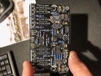
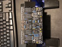
I'm going to match the transistors. Which ones should be matched in your opinion?
I have more silver micas on the way and I will remove the two ceramic caps I have left installed. Two things that were difficult the R26 10ohm 2w resistor was hard to source since it's a snug fit too! Also C14 has a Wima x2 in it. Is this fine or should I use something else. I do have these coming soon - B32521C3104J000 - B32521C3104J000 EPCOS (TDK) | Capacitors | DigiKey
Also did you just over the top the Cap with the R23?
So 300va 35-0-35 toroidal is recommended but my 300va 25-0-25 Will be ok for now.
Thanks Prasi


Hopefully this is a better testing scenario for the FH11. This is only 2 channels so I’m sure the PSU will sag more with 4 channels, but it is being built for an active 2-way bookshelf, so I won’t be using it even close to clipping.
10r and 5r dummy load resistors using a 1k sine wave.
At 10r - 107V Pk-Pk or ~143 Watts

At 5r - 99V Pk-Pk or ~245 Watts

Will try and figure out more tests as I learn to use the Oscilloscope better.
10r and 5r dummy load resistors using a 1k sine wave.
At 10r - 107V Pk-Pk or ~143 Watts
At 5r - 99V Pk-Pk or ~245 Watts
Will try and figure out more tests as I learn to use the Oscilloscope better.
Thanks Prasi,
I'm still waiting on parts. Should be here this week. Had to buy a new Soldering iron. I killed two hobby ones this week.
I'm going to match the transistors. Which ones should be matched in your opinion?
I have more silver micas on the way and I will remove the two ceramic caps I have left installed. Two things that were difficult the R26 10ohm 2w resistor was hard to source since it's a snug fit too! Also C14 has a Wima x2 in it. Is this fine or should I use something else. I do have these coming soon - B32521C3104J000 - B32521C3104J000 EPCOS (TDK) | Capacitors | DigiKey
Also did you just over the top the Cap with the R23?
So 300va 35-0-35 toroidal is recommended but my 300va 25-0-25 Will be ok for now.
Thanks Prasi
The Cap with R23 is not needed.
I posted recently some of the grounding options for the input ground.
let me find the post.
Sorry my mistake, 25VAC-0-25VAC will give +35VDC/-35VDC, so this should be just fine.
C14 is a zobel cap with 10mm pitch and 6.4 mm wide cap.
You can use any film cap here thats rated atleast 100-250 VDC.
R26 can be 1W also, if you have it handy.
transistor matching: match the Q1/Q2 without fail and thermally couple them.
Q10 is mounted on the output device or the heatsink where it can sense temperature.
regards
Prasi
Thanks Prasi!The Cap with R23 is not needed.
I posted recently some of the grounding options for the input ground.
let me find the post.
Sorry my mistake, 25VAC-0-25VAC will give +35VDC/-35VDC, so this should be just fine.
C14 is a zobel cap with 10mm pitch and 6.4 mm wide cap.
You can use any film cap here thats rated atleast 100-250 VDC.
R26 can be 1W also, if you have it handy.
transistor matching: match the Q1/Q2 without fail and thermally couple them.
Q10 is mounted on the output device or the heatsink where it can sense temperature.
regards
Prasi
Do you have any photos of what you done with your AX14 regarding Q1 & Q2 and Q10?
Thanks Prasi!
Last edited:
Thanks Prasi!
Do you have any photos of what you done with your AX14 regarding Q1 & Q2 and Q10?
Thanks Prasi!
Hello Hatless,
Just put some thermal goop between the 2 transistor's plastic bodies and use a cable tie so that they are in contact always.
Redirect Notice
even in this case, they are not face to face, but still good thermal contact can be obtained via tying them together with thermal goop in between.
For Q10, run short wires like in attached image.
DC Servo MOSFET Amplifier
Last edited:


Only thing with Q1 and Q2 being coupled together is they are not back to back like they are in the Honey Badger Amplifier. So should I just have Q1 spoon Q2?
View attachment 770913 View attachment 770914
yes post #11557
")
- Home
- Amplifiers
- Solid State
- 100W Ultimate Fidelity Amplifier