Error 404 - Forum Page Missing
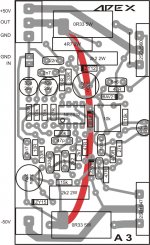
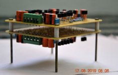
mr ades and dear apex in this picture i made apex fh11
see and enjoy...but dont work properly
2n5551 be hot/have hom in sspeaker/pop up sund when power be start.....im angryy
http://s4.picofile.com/file/8363574750/IMG_20190403_192542.jpg
see and enjoy...but dont work properly
2n5551 be hot/have hom in sspeaker/pop up sund when power be start.....im angryy
http://s4.picofile.com/file/8363574750/IMG_20190403_192542.jpg
hi mr apex ...i do this....replase with 370R...i have not 330R....but its good..sound be very beter base and treble is power full..perfect....power mosfet's dont hot afer 15 minutes.mje350/2n5551's not hot..just a few warm..can i use 470R for beter sound?Replace 150R resistor with 330R.
oh i forget tell that...when i turn on power pup nois is lower.how i can kill pup noise when power be on?
mr apex you made me happy...tnx...i send best wishes for you from ultimate land..
Last edited:
A3
Regards
Gurpreet
Hello Mr Miles, What is output power of A3. I can't found shematic of A3, please can u post the A3 amplifier shematic.A3 Pcb size 50x90mm.
Regards
Gurpreet
Attachments
Hello Mr Miles,
Does AX14 need Zobel Network if yes, values of resistor and inductor data, cos in the circuit it is not shown and can you briefly tell how to bias AX14.
Thanks and regards.
Anoop.
PS: Is there any scope for a new PCB design ? Because I have done a new design.
Does AX14 need Zobel Network if yes, values of resistor and inductor data, cos in the circuit it is not shown and can you briefly tell how to bias AX14.
Thanks and regards.
Anoop.
PS: Is there any scope for a new PCB design ? Because I have done a new design.
Inductor data
I'm really sorry was in a hurry so I asked about Zobel Network, actually I was only asking about the output inductor and its winding data and if there is any resistor then its value too.
Regards,
Anoop
Hello Mr Miles,
Does AX14 need Zobel Network if yes, values of resistor and inductor data, cos in the circuit it is not shown and can you briefly tell how to bias AX14.
Thanks and regards.
Anoop.
PS: Is there any scope for a new PCB design ? Because I have done a new design.
I'm really sorry was in a hurry so I asked about Zobel Network, actually I was only asking about the output inductor and its winding data and if there is any resistor then its value too.
Regards,
Anoop
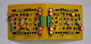
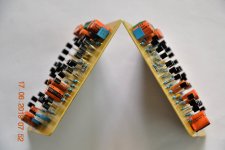
Apex P30 Success....!!!
Hi,
Completed Apex P30. Transparent sound....Feels Happy!!!
Thanks to Mr. Mile and everyone supported during the build...!
Regards,
Sumesh
Hi,
Completed Apex P30. Transparent sound....Feels Happy!!!
Thanks to Mr. Mile and everyone supported during the build...!
Regards,
Sumesh
Attachments
Congrats Sumesh ")
Regards
Sha
Regards
Sha
Hi,
Completed Apex P30. Transparent sound....Feels Happy!!!
Thanks to Mr. Mile and everyone supported during the build...!
Regards,
Sumesh
hi..can u help me to fix a problem abut my fh11 apex?Very nice Sumesh!
So - I populated a whole new board, testing every component I took out of the old board and replaced if out of spec. I used all new BD139, KSA/KSC and IRFPs along with (1) of the 3 2N5551s that seemed a little low on gain.
The SAME issue persists - anything higher than ~50Vdc PSU on I can't get the bias to stay constant, It slowly moves upward +25mV (then I turn it off)
- on note, is that the other channel I can reduce the bias much lower, like down to 1mV, where this "problem" channel will not go lower than 8mV, regardless of PSU voltage (35, 40, or (48.5, which 60V PSU w 60W DBT in series - bias won't go below 12.5mV)
What I did differently this time:
-I mounted the BD139 with flying leads on top of the IRFP240
-I don't have a O-scope - so I can't test oscillation that way
-I don't have a curve tracer - only a cheap transistor tester, so I grouped the transistors by Hfe so the gain wouldn't be way off on any of them. Also confirmed with B&K multi-meter tester that has transistor function
-Oscillation - I will try increasing C6 and C1/C2 to higher values this weekend and hopefully will fix the runaway.
FH11 UPDATE - it totally works and sounds very good---BUT I still have an issue with the bias on one channel (re-built channel). The bias goes no lower then 8.5mV on smallest PSU (+/-35Vdc), and 19mV on +/-65Vdc PSU. Plays fine on both voltages with no DC offset issues or thermal runaway, but the other channel bias can be set at 9mV at +/-65Vdc (as low as 4mV on +/-35Vdc) after warm up.
I have not changed any capacitors - only put the BD139 on flying leads and attached to the hottest running IRFP240.
Can I change something to be able to set the bias lower? When I listen to music at +/-65Vdc, it starts at 22mV and after about 10 minutes settles down to ~18.5mV. When playing music I can get it to 30mV at 80% volume (which is very loud) but don't want to blow it up again, so I have kept pretty low.
Hoping if I can get the bias down like the other channel, ~10mV after warm-up, would give additional SOA.
BTW - heat sink/transistors don't get over 100-degree F, with both channels running at 90-95db for 30 mins. Which I generally wouldn't play that loud. So I don't think there is anything wrong with the amplifiers, I appear to have some variance in part matching contributing to the bias differences.
e
but i have just a few hom nois
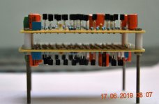
pleas see my pcb design in this link:
http://s4.picofile.com/file/8363574750/IMG_20190403_192542.jpg
i made fh11...in first i see that mje350 & 2n5551 be very hot...i have hi bias sound not very clear....but mr apex tell me replase 150R with 330R...i do this and result be very good....it work properly and sound be clear and good ..FH11 UPDATE - it totally works and sounds very good---BUT I still have an issue with the bias on one channel (re-built channel). The bias goes no lower then 8.5mV on smallest PSU (+/-35Vdc), and 19mV on +/-65Vdc PSU. Plays fine on both voltages with no DC offset issues or thermal runaway, but the other channel bias can be set at 9mV at +/-65Vdc (as low as 4mV on +/-35Vdc) after warm up.
I have not changed any capacitors - only put the BD139 on flying leads and attached to the hottest running IRFP240.
Can I change something to be able to set the bias lower? When I listen to music at +/-65Vdc, it starts at 22mV and after about 10 minutes settles down to ~18.5mV. When playing music I can get it to 30mV at 80% volume (which is very loud) but don't want to blow it up again, so I have kept pretty low.
Hoping if I can get the bias down like the other channel, ~10mV after warm-up, would give additional SOA.
BTW - heat sink/transistors don't get over 100-degree F, with both channels running at 90-95db for 30 mins. Which I generally wouldn't play that loud. So I don't think there is anything wrong with the amplifiers, I appear to have some variance in part matching contributing to the bias differences.
but i have just a few hom nois
pleas see my pcb design in this link:
http://s4.picofile.com/file/8363574750/IMG_20190403_192542.jpg
Last edited:
- Home
- Amplifiers
- Solid State
- 100W Ultimate Fidelity Amplifier