Prasi I am asking to Juan .2nd see what write Juan Sir not Juan . every time I ask Sir words.
Although I dont understand what you meant by above post, reply is best given by following two quotes (its actually what I meant in post # 10836)
1. "Chop your own wood and it will warm you twice" (signature by 44250)
2. "Give a man a fish and you feed him for a day; teach a man to fish and you feed him for a lifetime." again posted by 44250
Its helped me a lot in making PCB designs.
Also fawning (Calling Juan , "Juan Sir") isn't going to get you anywhere near your diy dreams.2nd see what write Juan Sir not Juan . every time I ask Sir words.
Last edited:
Sorry that I have to come back again I already send a message to Sunny please don't ask me to check your work or any modification on any of design is up to you to do changes on your own I'm not a engineer I'm jusylike any diy member here that love to build your own stuff so please try to figure it out yourself I did that a few year ago and I thing I'm good now ") if I did it you too can achived
if I did it you too can achived
Best Regards
Juan
if I did it you too can achived Best Regards
Juan
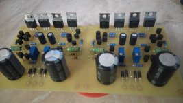
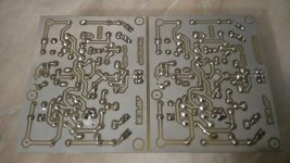
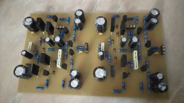
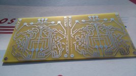
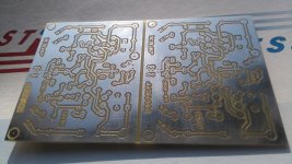
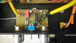
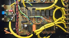
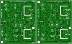
from posts 10824-10826. i made a mistake at MM-MC phono preamplifier,so will post all files only when i test all from pictures:
Attachments
NIce boads
Beautiful pcbs...
Toner transfer or some other technique?
from posts 10824-10826. i made a mistake at MM-MC phono preamplifier,so will post all files only when i test all from pictures:
Beautiful pcbs...
Toner transfer or some other technique?
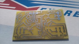
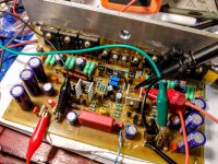
yes they are, but I did not made them(this time I have only soldiered them)-i paid a man to do them for me. I believe they were made with photo sensitive film, I have seen many toner transfer made pcb's from wich most were really good made - but this is just one step further in precision.
from posts 10824-10826. i made a mistake at MM-MC phono preamplifier,so will post all files only when i test all from pictures:
Tests completed...?
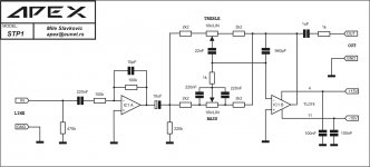
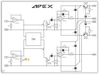
it will work with APEX preamp with tone controles:
Mile, is it safe to decrease amplifying ratio to 1? I wish to put 22k instead 10k at input, and switch with 18k resistor in parallel to achieve two amplifying ratios: 1 and 2,2. would it oscillate?
Mile, is it safe to decrease amplifying ratio to 1? I wish to put 22k instead 10k at input, and switch with 18k resistor in parallel to achieve two amplifying ratios: 1 and 2,2. would it oscillate?
Use input OP as buffer if you don't need gain like in first version of this preamp or use this circuit.
Attachments
Tests completed...?
yes. i made a mistake at MM-MC phono preamplifier,so later i will post corrected files. i have also decreased current of a-class shunt to achive less heating in inclosure by increasing 22r to 47r (for pair of phono) and to 62r (for preamp with tone controle). i have put 22k at input of preaplifier with tone controle and a switch with 18k in parallel with that 22k to achive amlifying ratio of 1 and 2,2. it is not necessary but that is what i wanted.
YouTube
Attachments
-
 aaaaac.jpg725.9 KB · Views: 1,543
 -
 aaaaaab.jpg576.8 KB · Views: 1,603
 -
 aaaaa.jpg767.5 KB · Views: 1,726
 -
 aaa.jpg706 KB · Views: 1,832
 -
MM MC bakar gledan kroz pločicu sa strane elemenata.pdf66.5 KB · Views: 216
-
MM MC raspored elemenata.pdf86.7 KB · Views: 214
-
 MM MC izgled jpg.JPG832.6 KB · Views: 1,579
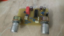
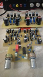
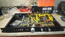
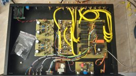
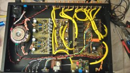
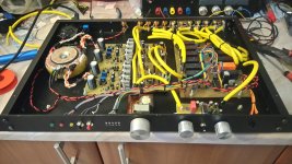
I have listened MM MC for a few hours now,and my first impressions are really good! I am not to experienced with phono theme, I had one phono preamp before this one. it was IC-based and it had (at my opinion) too much amplifying and it bursted a bit at high frequencies. MM MC does its job much more natural and pretty equally at all frequencies, from bass to treble. i think it should have a bigger amplifying ratio but it is quite enough as it is,all in all. for sure,it is a step further than I was until now.
Preamp with tone controles works also really nice,and whole system is really quiet even with everything on max and with MM MC as a signal source. quite pleasantly surprised!
Preamp with tone controles works also really nice,and whole system is really quiet even with everything on max and with MM MC as a signal source. quite pleasantly surprised!
Hello friends. I want to build the HX-11 class H but I would like to make some changes such as adding a pair of transistors more per rail (total six transistors) to make use of a big transformer that I got from an amplifier. I think one of the changes I have to make is replace the diodes that pass +/-VL. The power supply provides +/-35V, +/-75V. Any suggestion, I would thank you.
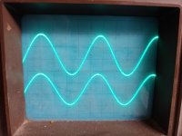
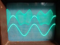
Guys, I still fighting with one channel of my Apex A40.. I am able to set bias,offset, but when i increase voltage over +-9V signal looking very strange... I did some mistake before, mostly solved...any idea?
I did some mistake before, mostly solved...any idea?Attachments
have you resolved problem? I have had problem with bias stability but oscilloscope had not showed me such problems... i do not know what would be a problem in your case, but it seems it is in "positive" side of power amplifying, I would start by checking that side of an amplifier board. compensations on that side,transistors pinout, value of resistors at their place... i have had problems with different markings of capacitors, so instead of (in my that one case) 330pF I have installed 33pF. manufacturer of capacitors I have had in that moment marks capacitors in a different way than others, and I have bought them as 330pF. naturally, amplifier had "seen" that and it was not glad,so it had oscillated.
hello
i need a hayberide preamp with tube and transistor
the sound must be warm and best quality
any one have sugestion please?
Pls contact @vzaichenko
Virtual Zero Audio Store
Hi,
please find attached herewith pdf files and other documents.
Which version of schematic is this? 14, 14.1, 14P or something else?
Guys, I still fighting with one channel of my Apex A40.. I am able to set bias,offset, but when i increase voltage over +-9V signal looking very strange...
Amplifier is unstable and breaking into oscillation.
Increase C9/10.
R21/22 can affect oscillation too, I usually use 10R in those positions.
tb3
good sr mile
can you help me with this detail
regards
You must disconnect tone control output, tone control input can stay connect and output must be open.
Regards
good sr mile
can you help me with this detail
regards
Attachments
- Home
- Amplifiers
- Solid State
- 100W Ultimate Fidelity Amplifier