1000W into 4r0 requires >89Vpk and >22Apk.
Do you think this amp connected to +-95V PSU can deliver that into a resistive load?
Have you any idea of the peak current demand of a reactive load?
Have you any idea what size of heatsink is required to keep this amp cool?
What precisely makes this design awesome
Do you think this amp connected to +-95V PSU can deliver that into a resistive load?
Have you any idea of the peak current demand of a reactive load?
Have you any idea what size of heatsink is required to keep this amp cool?
What precisely makes this design awesome
The only way for that (or any other amp using +/-95V) to put out 1000 watts is to either regulate the supply or run 2 ohm load with a practical one.
I'm sure the amp would *work*, with possibly minor modifications. Expect about 700W. The probelm with simulators is the "Vdc" element, that stays at 95V regardless of what kind of torture you put it through. Real ones aren't so well behaved.
I'm sure the amp would *work*, with possibly minor modifications. Expect about 700W. The probelm with simulators is the "Vdc" element, that stays at 95V regardless of what kind of torture you put it through. Real ones aren't so well behaved.
Well I think it might work because it is designed by trusted designer. Why do you think it wont output 1000W at 100V. Then what V is needed for 1000W.
You all people just talk about every design that it is not possible to deliver that amount of power but none of you showed some good REAL 1000W designs.
If 100V is little then why do we use transformers at all? Why don't we make power amplifier directly from the mains 240V just we will stabilize it using capacitors and diodes. LOL
I mean come on people... there are 5000W amplifiers. What voltage do they use? with your math they should use at least 400V supply.
Last edited:
.....................
If 100V is little then why do we use transformers at all? Why don't we make power amplifier directly from the mains 240V just we will stabilize it using capacitors and diodes. ................
Because that would be incredibly stupid and dangerous !!!! Which is why even discussion of that topic is banned on the forum.
.
Because that would be incredibly stupid and dangerous !!!! Which is why even discussion of that topic is banned on the forum.
.
Then how can I make 5000W amplifier?
I DON'T NEED IT I just want to make it so I can show it everywhere and I can boast around.
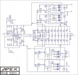
Ok this is the 2nd schematic i have seen where there are 2 sets of driver transistors and the output bank is split into two sections. There has to be some problems with this type of design. each output section has to run slightly different. how do you balance the sections??
Here 500W version of this one for 8Ohms.
This is something like parallel wiring. I think it is same if you put 2 in pair of those power transistors.Ok this is the 2nd schematic i have seen where there are 2 sets of driver transistors and the output bank is split into two sections. There has to be some problems with this type of design. each output section has to run slightly different. how do you balance the sections??
Attachments
Last edited:
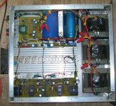
Yes that is the PCB and it is COMPLETE AND TESTED/WORKING project and it is very popular on balkan forums. Also "Boro" has lot of audio project on his website. You can check them on this link.
Moji Audio projekti
Just click on the "Pojacala" link at the left menu and there is list of great amplifier projects.
Moji Audio projekti
Just click on the "Pojacala" link at the left menu and there is list of great amplifier projects.
Well I think it might work because it is designed by trusted designer. Why do you think it wont output 1000W at 100V. Then what V is needed for 1000W.
You all people just talk about every design that it is not possible to deliver that amount of power but none of you showed some good REAL 1000W designs.
I *have* shown an amp that puts out 1kW. The power supply uses three transformers in series to produce +/-126V, which reduces to +/-102V with a sine wave and 4 ohm load and +/-88V with 2 ohms. That's what a real supply does, unless you use a trafo the size of a small moon. You can't run IRFP240's on +/-126V (or MJL21194's) unless you cascode them. So you either live with the limits of a real supply, which will put you in the 700W range, use a different design which can take more Vcc, or become an expert SMPS designer.
I mean come on people... there are 5000W amplifiers. What voltage do they use? with your math they should use at least 400V supply.
The supply voltages can be in the 400V range, but usually more like 300. The power supplies are switch mode, and usually resonant-mode with PFC, and quite often regulated. That's not trivial or cheap to build. That's why those amps cost $5000 and why early DIY attempts to build such supplies end up in a fireball. I gurantee you the first one that big that Eva built ended up requiring a fire extinguisher, too.
I *have* shown an amp that puts out 1kW. The power supply uses three transformers in series to produce +/-126V, which reduces to +/-102V with a sine wave and 4 ohm load and +/-88V with 2 ohms. That's what a real supply does, unless you use a trafo the size of a small moon. You can't run IRFP240's on +/-126V (or MJL21194's) unless you cascode them. So you either live with the limits of a real supply, which will put you in the 700W range, use a different design which can take more Vcc, or become an expert SMPS designer.
The supply voltages can be in the 400V range, but usually more like 300. The power supplies are switch mode, and usually resonant-mode with PFC, and quite often regulated. That's not trivial or cheap to build. That's why those amps cost $5000 and why early DIY attempts to build such supplies end up in a fireball. I gurantee you the first one that big that Eva built ended up requiring a fire extinguisher, too.
heheheheheheh good answer. Thank you

often designers forcus on producing a realy nice amplifier ...performance and sound is outstanding ...then of course no PA amplifier will stand this ammount of power (either possible or not regarding the power ) without eficient and enough protections on each and every section
Dr Bora very correctly stated that "i dont design idiot proof amplifiers " but then again any amplifier at this power should be designed as "idiot proof "
( in a way that should also be a chalenge for designers to produce something like powerfull+idiot proof+sounding good )
many of us take place in discussion on how much power here and how much power there but posts about complete designs that cover all sections arent that many arround
thanks sakis
I believe the amp is specified at 1kW into 4 ohms. It will do so with the power supply lines as stated wit saome volts of margin but requires a truly monumental transformer (think 2-3kVA) and lots of smoothing caps. A smaller power supply will do it in peak mode but realistically it's more likely to do 700W into 4 ohms long term.
many of us take place in discussion on how much power here and how much power there but posts about complete designs that cover all sections arent that many arround
What do you want? ISO-compliant released drawing, assembly instructions and a complete BOM? They don't exist. Why? When the amp is put together using what's on hand, by hand, without a machine shop, in the order that it goes together, solving problems as it goes along, and taking a year or more to do it - those sort of 'instructions' aren't really needed.
And for those with the proper manufacturing facilities, you're not going to get their company proprietary secrets out of them.
Attachments
but requires a truly monumental transformer (think 2-3kVA) and lots of smoothing caps. .
Try 6 to 10 kVA to get that kind of regulation. About the size of a small moon, and between $500-$1000.
No people I think we should use SMPS.
Here is nice SMPS from bora. Hi claims it can produce up to 600 W and more.
Can someone tell me if I can use ferrite transformer from ATX/AT power supply?
This is two sided PCB project. What do you think about this one? Is it good?
Thank you.
ALL COPYRIGHT GOES TO DR.BORA.
Here is nice SMPS from bora. Hi claims it can produce up to 600 W and more.
Can someone tell me if I can use ferrite transformer from ATX/AT power supply?
This is two sided PCB project. What do you think about this one? Is it good?
Thank you.
ALL COPYRIGHT GOES TO DR.BORA.
Attachments
Last edited:
- Status
- This old topic is closed. If you want to reopen this topic, contact a moderator using the "Report Post" button.
- Home
- Amplifiers
- Solid State
- 1000W amplifier -- This is great schematic