As always nice build Terry, cheers to you but I have a question about the design itself.
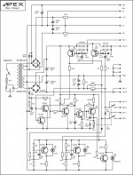
What I do not understand with this design, is why the, so called, "evil" feedback cap "C6" is being used? I thought the whole idea of using a DC servo-controlled design, is to eliminate the evil ecap in the FB path, that is for controlling the DC offset and allow for DC gain? Unless the servo can not compensate for the amount of DC offset without using C6, which brings the whole design topology into question.
What I do not understand with this design, is why the, so called, "evil" feedback cap "C6" is being used? I thought the whole idea of using a DC servo-controlled design, is to eliminate the evil ecap in the FB path, that is for controlling the DC offset and allow for DC gain? Unless the servo can not compensate for the amount of DC offset without using C6, which brings the whole design topology into question.
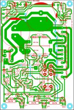
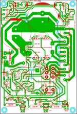
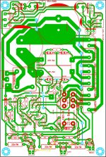
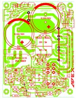
I looked at the board layout and there is a distinct lack of star grounding, so that the high currents from the rail decoupling capacitors get injected into small signal ground - that's probably enough to risk oscillation.
This is made worse by the ground trace being pretty thin and split two-ways, rather than flood-filled plane - most of the top side is unused and could be used for decent ground.
Dear Mark, this pcb ( one of my first) was done with some inputs, read back. input ground is separate.
This is an old styled DIY pcb with no provision for top layer but for jumpers
") . Anyone with copper clad and few parts in his bin can build this.
. Anyone with copper clad and few parts in his bin can build this.regards
prasi
As always nice build Terry, cheers to you but I have a question about the design itself.
What I do not understand with this design, is why the, so called, "evil" feedback cap "C6" is being used? I thought the whole idea of using a DC servo-controlled design, is to eliminate the evil ecap in the FB path, that is for controlling the DC offset and allow for DC gain? Unless the servo can not compensate for the amount of DC offset without using C6, which brings the whole design topology into question.
There is no "C6 evil feedback cap" in the design that Terry built. The design is according to following sch.
DC Servo MOSFET Amplifier
Nice build Terry,
I am sure there is someway to configure clip leds, Mr. Mile can tell us.
regards
prasi
A side note: you have created a great shortfall of diamond plates which could have been used elsewhere to support infrastructure development by Governments!
Hi Prasi,
The PSU I used is the original FX100 PSU. It has clip LED's built into the circuit. I tried to use them but every time I drove the amp hard enough to make it clip it blew the LED. I thought I had wired it wrong initially but after 4 LED's I realized it is hitting them too hard.
Attachments
Hi Prasi,
The PSU I used is the original FX100 PSU. It has clip LED's built into the circuit. I tried to use them but every time I drove the amp hard enough to make it clip it blew the LED. I thought I had wired it wrong initially but after 4 LED's I realized it is hitting them too hard.
Use 22k 1W instead 6k8 1W in clip circuit...
Use 22k 1W instead 6k8 1W in clip circuit...
Thanks Mile,
I knew you would have a fix. Thanks for this design by the way. Very cool amp and thank you Prasi for the neat boards. They were a pleasure to build.
Blessings, Terry
Thanks Mile,
I knew you would have a fix. Thanks for this design by the way. Very cool amp and thank you Prasi for the neat boards. They were a pleasure to build.
Blessings, Terry
Protect LED also use 6k8, go to 22k... FX100 is one of my favorite PA amp,
Regards
That didn't work. First flash and the LED is gone. I wonder if I can protect them with a Zener? BTW the protect LED is fine. Not even that bright.
Clip circuit on your PSU bord is not from schematic in post 805...
I found it.
DC Servo MOSFET Amplifier
No schematic, just a layout from sonal. I see he added the clip circuit from something else that Mile used somewhere. I'm going to start over on the PSU and use the schematic from post 801.
DC Servo MOSFET Amplifier
No schematic, just a layout from sonal. I see he added the clip circuit from something else that Mile used somewhere. I'm going to start over on the PSU and use the schematic from post 801.
I missed one diode.
Some tracks missing...
Use this PSP100 for FX100 with 3 pairs.
Attachments
Last edited:
Okay, I see now, this thread references more than one design, I was looking at A100, but Terry built FX100, carry onThere is no "C6 evil feedback cap" in the design that Terry built. The design is according to following sch.
Some tracks missing...
Use this PSP100 for FX100 with 3 pairs.
The drawback it that the PSP100 doesn't have the +-15V circuit for my XLR pre.
Can you post files of your XLR pre?The drawback it that the PSP100 doesn't have the +-15V circuit for my XLR pre.
- Status
- This old topic is closed. If you want to reopen this topic, contact a moderator using the "Report Post" button.
- Home
- Amplifiers
- Solid State
- DC Servo MOSFET Amplifier