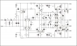
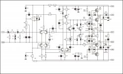
If input was overloaded that produce DC on zeners for limiter (C2)I'm not a big fan of solid state, but I have some questions!
I do not understand why you have C2 as well as C1.
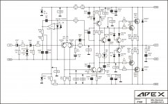
What are the big 0.22R resistors for?
What is the loop feedback gain/amount?
What is the crossover distortion with the loop feedback removed?
I think you need a bias so you can also run in class AB (my opinion)
Why is there no bypass cap for the zener of the driver circuit?
Why is there no Zobel network (LC) on the output?
0.22R equalise current from unmached mosfets
With BD139 on heatsink you can run amplifier in class AB
Not nessesery to bypass zener
There is Zobel network on output but RC shunt.
Regards
If you want 4 pairs of output I sugest you to build this amp:
http://www.diyaudio.com/forums/solid-state/162043-mosfet-amplifier-irfp240-irfp9240-24.html
Regards
i only have n channel mosfet in stock

regards
If input was overloaded that produce DC on zeners for limiter (C2)
Good point! Do you still need R1 and C1 ?
I like the C14 and C16 bypass, you may think of bypassing C2 and C6
Otherwise looks fairly clean, I'd be tempted to increase local feedback and decrease global NFB next, although your GNFB goes through less stages than some!
This transformer is better to use with this amplifier:Hi apexaudio
Bias it problem if Use +-70Vdc ?
I Have 50Vac transformer 6 Ea. In stock.
Regards
http://www.diyaudio.com/forums/solid-state/162043-mosfet-amplifier-irfp240-irfp9240-25.html
Regards
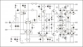
Q1 and Q2 from post #12?hi apex,
for Q1 and Q2 is it supposed to be npn as BC546 is npn or in the schematic it is supposed to be another type of transistor?
Regards,
Regards
Q1 and Q2 are PNP type BC556,yes in reference to post #12 schematics.
regards,
Regards
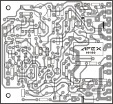
I must made some improvment in VAS. Mosfet output stage in class H can be used in other amplifiers.Hi..Apex..thanks alot yours sharing this H100...Please give this schematic value componen and layout PCB .....
Regards
Attachments
hI Miles,
I have built the ckt using the pcb in post#33 , using +/- 48 psu unloaded but I'm getting +44v in the output ( reference to gnd) connecting ground wire to the input the same result. Replaced the tl071 and bd139 but also the same. I've used the specified tranny IRF240/IRFP9240, is the yellow LED supposed to lit when the amp is normally operational? Do you have some guide on what should be the nominal voltage reading in the particular point on that circuit if there are that will be a big help in the troubleshooting.
Regards,
Stcboy
You must connect separate ground wire from PSU to input GND. Yellow LED lit when the amp is normally oprational.hI Miles,
I have built the ckt using the pcb in post#33 , using +/- 48 psu unloaded but I'm getting +44v in the output ( reference to gnd) connecting ground wire to the input the same result. Replaced the tl071 and bd139 but also the same. I've used the specified tranny IRF240/IRFP9240, is the yellow LED supposed to lit when the amp is normally operational? Do you have some guide on what should be the nominal voltage reading in the particular point on that circuit if there are that will be a big help in the troubleshooting.
Regards,
Stcboy
Regards
Attachments
- Status
- This old topic is closed. If you want to reopen this topic, contact a moderator using the "Report Post" button.
- Home
- Amplifiers
- Solid State
- DC Servo MOSFET Amplifier