Would you please share the schematics? Thank you!
Best regards!
Schemaic is in post #1014
Schematic says with limiter, PCB layout says without limiter. So, what's the truth?
Best regards!
Schematic without limiter
Attachments
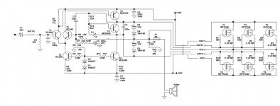
Simple mosfet amplifier pcb without limiter.
Attachments
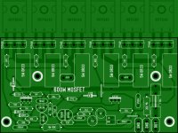
600w with this pcb isn't possible at all.Very thin traces, very close positioned transistors,only 3 trans/rail e.t.c, e.t.c
600W is not power of this amp it is amplifier name, power is 250W
Hi Apex,
Since you are not using lateral mosfets in this schematics, I was wondering how thermal tracking and compensation is achieved without a VBE multiplier?
Just curious,
Jacques
There is VBE multiplier with BC546
There is VBE multiplier with BC546
True, I see a MPSA06/BC546 there but not in thermal contact with the outputs?
Last edited:
Just a few thoughts:
-3 pairs of output devices for 94V rail on 4 Ohms is wishful thinking.
-6-7mA of VAS current is again a bit of wishful thinking for proper output stage drive.
-With such a high power supply you really need thermal compensation, thus the Vbe multiplier's transistor needs to be in close contact with the heatsink, TO92 devices are not suited for the job, TO126 or even TO220 are much better for this.
-The VAS transistors need proper heatsinking, thus, the pcb layout must take that into account.
-The CLG is rather high, that combined with the low value miller cap, could present the risk of instability in some conditions ( i haven't simulate it, thus i cannot be sure it is so ).
-I wont even comment the pcb layouts presented on #1018 and #1024.
I'm sorry if i am upsetting someone with this entry, but there it is, take it as you wish.
have a nice day.
Just a few thoughts:
[...]
have a nice day.
Marian: no need to be so negative.
Apex has a lot of hands-on experience and I am learning a lot from the number of original schematics he submitted here.
Theory is good but it is always nice to have different views based on experiments even if they clash a bit with established
(and sometimes stale) dogmas.
Cheers,
Jacques
600W is not power of this amp it is amplifier name, power is 250W
Just a few thoughts:
-3 pairs of output devices for 94V rail on 4 Ohms is wishful thinking.
-6-7mA of VAS current is again a bit of wishful thinking for proper output stage drive.
-With such a high power supply you really need thermal compensation, thus the Vbe multiplier's transistor needs to be in close contact with the heatsink, TO92 devices are not suited for the job, TO126 or even TO220 are much better for this.
-The VAS transistors need proper heatsinking, thus, the pcb layout must take that into account.
-The CLG is rather high, that combined with the low value miller cap, could present the risk of instability in some conditions ( i haven't simulate it, thus i cannot be sure it is so ).
-I wont even comment the pcb layouts presented on #1018 and #1024.
I'm sorry if i am upsetting someone with this entry, but there it is, take it as you wish.
have a nice day.
Zingy states 600W in his attachment.Marian: no need to be so negative.
Apex has a lot of hands-on experience and I am learning a lot from the number of original schematics he submitted here.
Theory is good but it is always nice to have different views based on experiments even if they clash a bit with established
(and sometimes stale) dogmas.
Cheers,
Jacques
Apex replies not 600W, 250W.
MarianB gives us the warning "-3 pairs of output devices for 94V rail on 4 Ohms is wishful thinking." and further warnings.
jacquesA suggests "Marian: no need to be so negative. "
Apex and Marian are telling us that there is a limit to how much to expect.
Yet Jacques wants us to believe otherwise.
MarianB is correct !
Zingy states 600W in his attachment.
Apex replies not 600W, 250W.
MarianB gives us the warning "-3 pairs of output devices for 94V rail on 4 Ohms is wishful thinking." and further warnings.
jacquesA suggests "Marian: no need to be so negative. "
Apex and Marian are telling us that there is a limit to how much to expect.
Yet Jacques wants us to believe otherwise.
MarianB is correct !
Amp can not work with +/94V rail on 4 Ohms but will work with +/-64V.
250W into 8r0 is equivalent to 63.2Vpk and 7.91Apk
That 250W into 8ohms could be obtained from supply rails of ~+-75Vdc.
Would that be OK?
250W into 4r0 is equivalent to 44.7Vpk and 11.2Apk.
supply rails of +-64Vdc seems to me to be too high for the 4ohms loading, with only a 3pair output stage using 150W devices.
4pair of 150W devices seem more appropriate for 4ohms loading @ +-64Vdc.
Yet Jacques wants us to believe otherwise.
Hey AndrewT,
You are not correct and overinterpreting. Please stop distributing points.
My only concern here was the absence of thermal contact between the VBE multiplier and the outputs. This was already a concern at the very beginning of this thread but was never fully answered.
This is a chance to give your expert opinion
.Cheers,
Jacques
Marian: no need to be so negative.
Apex has a lot of hands-on experience and I am learning a lot from the number of original schematics he submitted here.
So we should not point out the problems just because the author is famous?
I say just the opposite, just because the author is famous he should pay much closer attention to what he posts here, sometimes there is such a thing as too simple of a design. The schematic is drawn in an awful way, and has the problems i have already mention. And the pcb layout is... enough to say it's weak. I am sorry if am insulting but i for one have some standards for my designs and when i see something i do not like, i point it out, no matter the author.
Amp can not work with +/94V rail on 4 Ohms but will work with +/-64V.
Why then is there 94V and 4R in the schematic?
So we should not point out the problems just because the author is famous?
I say just the opposite, just because the author is famous he should pay much closer attention to what he posts here, sometimes there is such a thing as too simple of a design. The schematic is drawn in an awful way, and has the problems i have already mention. And the pcb layout is... enough to say it's weak. I am sorry if am insulting but i for one have some standards for my designs and when i see something i do not like, i point it out, no matter the author.
Why then is there 94V and 4R in the schematic?
Just to pay attention, well designs circuits is not popular.
So we should not point out the problems just because the author is famous?
Not at all! I just found the tone of your post overly biased towards negativity.
In the view of the important contribution of the OP in this forum, I tried to bring
positive vibrations in the thread (and failed, obviously
 ). My mistake.
 This endless interpretation of other people's comments and opinions is useless and tiresome.
Could we please move on to a more technical discussion? Thanks.
Hint: I still would like to know how this amp can achieve thermal stability with a VBE multiplier not in contact with the outputs.
- Home
- Amplifiers
- Solid State
- MOSFET Amplifier IRFP240/IRFP9240