Member
Joined 2009
Paid Member
I've been thinking (and talking) about building something simple in Class A.
It's a junk box project, nothing fancy, trying to use whatever I can get my hands on. So I won't be making any pcb's.
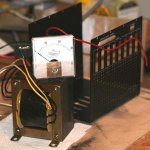
From a pair of Acopian psu's I scavenged 4 Trafo's and 4 panel meters, so 1 Trafo and 1 meter per amplifier makes for 4 'experiments'.
A colleague gave me 4 metal boxes, used (cut outs) which are too small. In fact they can just fit in the Trafo. I've got some extruded heatsink that's not that beefy but I can cut it up and attach it to the sides of the boxes.
I'm thinking only low power, a few W for use with a single driver full range speaker.
With too little space in the box, inadequate heatsink it's going to be a real BOTCH UP
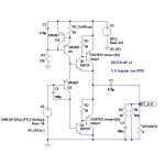
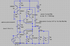
First up will be something JLH'ish. After 'borrowing proudly' from others who have gone before me the first circuit is looking like a simple JLH Follower. The output devices will be compound pairs to increase their input impedance. Unlike the original JLH I'm going to use only Sziklai pairs.
A couple of images, one of the parts I have on hand, the other showing the Follower. My CD player puts out a strong signal but I'm considering a preamp.
It's a junk box project, nothing fancy, trying to use whatever I can get my hands on. So I won't be making any pcb's.
From a pair of Acopian psu's I scavenged 4 Trafo's and 4 panel meters, so 1 Trafo and 1 meter per amplifier makes for 4 'experiments'.
A colleague gave me 4 metal boxes, used (cut outs) which are too small. In fact they can just fit in the Trafo. I've got some extruded heatsink that's not that beefy but I can cut it up and attach it to the sides of the boxes.
I'm thinking only low power, a few W for use with a single driver full range speaker.
With too little space in the box, inadequate heatsink it's going to be a real BOTCH UP
First up will be something JLH'ish. After 'borrowing proudly' from others who have gone before me the first circuit is looking like a simple JLH Follower. The output devices will be compound pairs to increase their input impedance. Unlike the original JLH I'm going to use only Sziklai pairs.
A couple of images, one of the parts I have on hand, the other showing the Follower. My CD player puts out a strong signal but I'm considering a preamp.
Attachments
Gareth,
I believe 160uA flowing through Q5/Q3 is insufficient; you might consider ramping this up to a mA or so in order to strongly drive Q1 and Q2. You would then need to trim R3 down to a similar current; but even so, you still have two CCSs fighting each other. I think it would work well, however, and give you that lovely SE sound.
Innovative circuit!
Hugh
To do this, I believe you'd need only put in a resistor of 680R from base Q2 to ground, and
Hi,
Hardly.I think it would work well, however, and give you that lovely SE sound.
Cool, it has shades of JLH. (but also different)
CFP's decrease output impedance over the traditional Darlington, by dividing the masters' Gm.
Should be totally stable into any load.
If you just put a 680 ohm resistor across the Vbe of Q2, Q1 will work harder and take a little more of the power. So if you're worried about balance, you might add the same value resistor across Q1.
- keantoken
Member
Joined 2009
Paid Member
Thanks for the input.
I notice that keantoken has a similar output stage in his headphone amplifier and has it operating on a breadboard with great sound, so I'm much encouraged by the practical demonstration.
Yup, the phase splitter is running on fumes, it wouldn't be difficult to change - perhaps I should try it both ways.
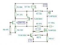
I've noticed that my junk box has an equal mix of PNP and NPN output devices. So I will have to build half the amplifiers with NPN and the other half PNP. I can also consider a 2nd option (remember I am to make 4 units total).
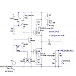
Option 2 (posted here) balances the use of junk box parts, but opens the question - does it alter the sound ? In simulations both options have a similar harmonic balance (H2>H3>H4>H5...). Option 2 looks more symmetrical, but doesn't appear to behave so and I assume a key reason is because the load current flows to ground - no virtual earth or split rails. This time there's plenty of current through the input device which serves only to allow proper biassing of the output. JLH also looked at a similar configuration, which he published in Wireless World, July 1970.
I notice that keantoken has a similar output stage in his headphone amplifier and has it operating on a breadboard with great sound, so I'm much encouraged by the practical demonstration.
Yup, the phase splitter is running on fumes, it wouldn't be difficult to change - perhaps I should try it both ways.
I've noticed that my junk box has an equal mix of PNP and NPN output devices. So I will have to build half the amplifiers with NPN and the other half PNP. I can also consider a 2nd option (remember I am to make 4 units total).
Option 2 (posted here) balances the use of junk box parts, but opens the question - does it alter the sound ? In simulations both options have a similar harmonic balance (H2>H3>H4>H5...). Option 2 looks more symmetrical, but doesn't appear to behave so and I assume a key reason is because the load current flows to ground - no virtual earth or split rails. This time there's plenty of current through the input device which serves only to allow proper biassing of the output. JLH also looked at a similar configuration, which he published in Wireless World, July 1970.
Attachments
The difference is that now both halves are operating in current amplifier mode while one used to be in voltage amp mode.
The difference between your circuit and the JLH is that yours is a voltage buffer while the JLH is a current amplifier. At first I though they were similar but now it looks like they are unique.
Something you may find interesting to play with:
Try a 22u cap in series with a 500k pot, and put this between the output and the base of Q4. Now the output stage will seem to "drive itself".... adjusting the pot will change the input impedance and at a certain value will remove all of the fundamental from Q3's Ie. It all depends on the load though.
- keantoken
Member
Joined 2009
Paid Member
The difference is that now both halves are operating in current amplifier mode while one used to be in voltage amp mode.
The difference between your circuit and the JLH is that yours is a voltage buffer while the JLH is a current amplifier. At first I though they were similar but now it looks like they are unique.
Indeed, although I like to view both options as Followers. The input signal finds it's way through the cascaded EF's to the output so perhaps one can think of both of these options as Current Buffers.
Try a 22u cap in series with a 500k pot, and put this between the output and the base of Q4. Now the output stage will seem to "drive itself".... adjusting the pot will change the input impedance and at a certain value will remove all of the fundamental from Q3's Ie. It all depends on the load though.
(great minds....) I simulated something like this a few months back. It was in fact my starting point! It came from an attempt to reproduce NP's Zen amplifier with it's modulated Aleph current source. It remains a good option but it has it's own drawbacks and the range over which the current source allows modulation is limited. The power-up characteristics of this approach is a bit nasty because you have a kind of positive feedback - a bootstrap as you say - which has produced some motor-boating in my simulations during power-on. It matters a great deal where you take the output from (before or after the output capacitor). I'll post this one up if it makes it back onto the drawing board.
By the way, it was remiss of me not to give thanks in this thread to Revintage & Kenpeter, who's posts elsewhere on the forum got my brain moving again after Christmas - hence I have to begin construction (though it will go very slowly so those who want quick results will be disappointed with me... Hugh, you'll have to keep the pressure on
)
Last edited:
Yes, I am pretty much sure it's not very practical, but there is one more interesting thing.
Put a small capacitor in parallel with the resistor - what happens? At HF the output stage draws more current because of Cob. So even if the CCS doesn't work that well for LF because of loading, it does have the capacity to almost completely null the affects of Cob in the output stage. I think I will throw together a few simulations to demonstrate exactly.
- keantoken
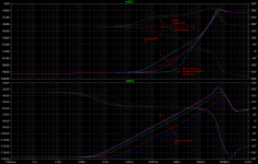
Just because I like making these graphs, I'm sure you understand already.
The optimal value in simulation is 56pF.
I believe this is a very useful possibility, and can decrease HF distortion. It may be a good mod to already existing amps. This aspect itself is independent of loading. So in fact, it should work without any drawbacks.
- keantoken
The optimal value in simulation is 56pF.
I believe this is a very useful possibility, and can decrease HF distortion. It may be a good mod to already existing amps. This aspect itself is independent of loading. So in fact, it should work without any drawbacks.
- keantoken
Attachments
Last edited:
Member
Joined 2009
Paid Member
Kean, I'm so pleased you have taken an interest in my thread, these insights are all the motivation I need ! - I'd like to know what you find with the HF experiment.
Option 1 with no collector load on Q3 does result in a nice balance between output devices, H2 is correspondingly better than if I introduce a load.
I've tried one more variation - but I must warn you that it isn't new and is probably something I should attribute to kenpeter or Lumba or a person from many years ago.... I have realized that when I follow a circuit and start changing it that I eventually end up somewhere familiar. I've done this a dozen times this year. You get all excited and then find yourself looking at something old. It's like all the topologies out there are secretly linked together by just a few changes (6 degrees of freedom ?). For example, the Rush Cascode could be twisted into an EF input buffer driving a common base voltage amplifier - if you want to set it up that way.
Anyhow, let's combine options 1 and 2 from my posts so far. Option 1 is the basic JLH follower where the upper output Sziklair pair is driven off the emitter of Q3. The other output needs the opposite phase so Q3 collector fills that need.
In option 2 I wanted to try and mix equally NPN and PNP output pairs so instead of needing Q3 to behave like a phase splitter I drive both outputs from the emitter of Q3. It's a bit boring perhaps because it resembles a Class B output but it performs wonderfully.
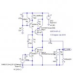
Now, let's keep the NPN and PNP output of option 2, but try to reintroduce the JLH follower from option 1. What we do is to drive both of the output devices with their own separate JLH phase splitting transistor. Both outputs devices will be driven from the emitter of their own input device, the collector signal from the input device is not used since we no longer need two different phases.
So we have two input devices and potentially two current sources (one of them is a current sink). We don't need these guys fighting and realizing that the current source design I've used is really just a Wilson current mirror in disguise we simple convert the current sink into a current mirror. Now the original current source is the 'master' and it sets the current through the output. Although not shown in my circuit at this point, emitter resistors for each current mirror device can be introduced and their ratio will allow control over the balance of drive signal to each output device - we can tune H2/H3 ratio as we please
I don't think it will take long for somebody to realize what name my 'double JLH follower' is known by... although perhaps not exactly in this form.
(can't get upload to work, I'll be back in tick....)
Option 1 with no collector load on Q3 does result in a nice balance between output devices, H2 is correspondingly better than if I introduce a load.
I've tried one more variation - but I must warn you that it isn't new and is probably something I should attribute to kenpeter or Lumba or a person from many years ago.... I have realized that when I follow a circuit and start changing it that I eventually end up somewhere familiar. I've done this a dozen times this year. You get all excited and then find yourself looking at something old. It's like all the topologies out there are secretly linked together by just a few changes (6 degrees of freedom ?). For example, the Rush Cascode could be twisted into an EF input buffer driving a common base voltage amplifier - if you want to set it up that way.
Anyhow, let's combine options 1 and 2 from my posts so far. Option 1 is the basic JLH follower where the upper output Sziklair pair is driven off the emitter of Q3. The other output needs the opposite phase so Q3 collector fills that need.
In option 2 I wanted to try and mix equally NPN and PNP output pairs so instead of needing Q3 to behave like a phase splitter I drive both outputs from the emitter of Q3. It's a bit boring perhaps because it resembles a Class B output but it performs wonderfully.
Now, let's keep the NPN and PNP output of option 2, but try to reintroduce the JLH follower from option 1. What we do is to drive both of the output devices with their own separate JLH phase splitting transistor. Both outputs devices will be driven from the emitter of their own input device, the collector signal from the input device is not used since we no longer need two different phases.
So we have two input devices and potentially two current sources (one of them is a current sink). We don't need these guys fighting and realizing that the current source design I've used is really just a Wilson current mirror in disguise we simple convert the current sink into a current mirror. Now the original current source is the 'master' and it sets the current through the output. Although not shown in my circuit at this point, emitter resistors for each current mirror device can be introduced and their ratio will allow control over the balance of drive signal to each output device - we can tune H2/H3 ratio as we please
I don't think it will take long for somebody to realize what name my 'double JLH follower' is known by... although perhaps not exactly in this form.
(can't get upload to work, I'll be back in tick....)
Member
Joined 2009
Paid Member
Wow Bigun, that's really cool! However Q7's Vce will cause imbalance and may interfere with the compensation. So I suggest finding a way to keep Q7's Vce the same as Q8.
I think so, but there may be some weird affects since Q1 and Q2 are separated, and I suspect the Cob of Q1 and Q2 won't both be compensated as well, the separated compensation paths for each may interfere. I think a simulation is in order.
- keantoken
I think so, but there may be some weird affects since Q1 and Q2 are separated, and I suspect the Cob of Q1 and Q2 won't both be compensated as well, the separated compensation paths for each may interfere. I think a simulation is in order.
- keantoken
- Status
- This old topic is closed. If you want to reopen this topic, contact a moderator using the "Report Post" button.
- Home
- Amplifiers
- Solid State
- Bigun's Botch Up amplifier