From the integrated amplifiers Mission Cyrus ONE and Cyrus TWO there are PDF schematics here:
https://www.hifiengine.com/manual_library/cyrus/1.shtml
https://www.hifiengine.com/manual_library/cyrus/2.shtml
https://www.hifiengine.com/manual_library/cyrus/3.shtml (incl. "i")
check out the overview for service manuals of the later models from Cyrus
https://www.hifiengine.com/manual_library/cyrus.shtml
and for Cyrus IIIi I did create a schematic diagram some years ago (see PDF upload) and compare to the genuine schematic published later - not too many errors in my own schematic
But where are schematics of the later models Cyrus 8, Cyrus 8vs, Cyrus 8vs2 and Cyrus 6 (not included in the associated service manuals) so as from the currently version of Cyrus ONE ?
By study the schematic diagrams of power amp sections of the various models I note, that only the Cyrus IIIi looks the most interesting of all (due current control global NFB mostly called "CFA").
It is similar to OMTEC's topology - go to post #12 under
https://www.diyaudio.com/community/...amplifier-ca-25-ca25-schematic-wanted.160949/
last image and this kind of NFB is discuss here:
https://www.diyaudio.com/community/threads/cfa-topology-audio-amplifiers.240712/
All the other models are designed as "VFA" as kind of NFB (maybe except the models Cyrus 8, Cyrus 8vs, Cyrus 8vs2 and Cyrus 6 from that no schematics to find - but is rather unlikely, since the XP versions of Cyrus 6 + 8 according the simplified schematics are also designed as VFA).
Is this anywhere described this fact on the Cyrus-website and justify why one did it that way ?
Or only those who know the circuit topology from power amp sections of all Cyrus integrated amplifier models know that ?
Under
https://www.cyrusaudio.com/products/cyrus-3i/
is mentioned only this:
The Cyrus IIIi is a conservatively rated 50W per channel integrated amplifier designed to become the core of a quality audio system. Following in footsteps of the well respected Cyrus I & II, the Cyrus IIIi is an ‘improved’ Cyrus III which has moved on to address the life style requirements of the 90s as well as having the ability for expansion into a fully integrated audio-visual system
Here some other threads without help:
http://www.diyaudio.com/forums/solid-state/153794-mission-cyrus-iii.html
http://www.diyaudio.com/forums/solid-state/153502-cyrus-3-a.html
http://www.diyaudio.com/forums/solid-state/146116-cyrus-3-cyrus-iii-amp-help.html
http://www.diyaudio.com/forums/solid-state/21901-cyrus-3-reconfigure-use-without-psxr.html
http://www.diyaudio.com/forums/solid-state/86367-cyrus-3-amplifier-component-mistakes.html
http://www.diyaudio.com/forums/solid-state/86122-cyrus-3-rescue.html
http://www.diyaudio.com/forums/solid-state/50824-cyrus-3-amp-problem.html
http://www.diyaudio.com/forums/solid-state/22595-cyrus-3-service-manual-anyone.html
http://www.diyaudio.com/forums/chip-amps/141464-cyrus-3-gainclone-project.html
http://www.diyaudio.com/forums/solid-state/120210-cyrus-iii-intergrated-amplifier.html
Thank you for your advice for finding schematic for power amp section of Cyrus 6+8
Attachments
-
Cyrus IIIi.power amp own created schem.pdf23.7 KB · Views: 155
-
Cyrus-IIIi (HA7Z) power amp section.pdf78.3 KB · Views: 136
-
Cyrus ONE power amp section iss 7 (old).pdf65.6 KB · Views: 168
-
Cyrus TWO power amp section iss 7 (old).pdf83 KB · Views: 122
-
Cyrus III (HA7A3157) power amp section.pdf44.7 KB · Views: 118
-
Cyrus 5 power amp section.pdf52.8 KB · Views: 101
-
Cyrus 7 power amp section.pdf54.5 KB · Views: 116
-
Cyrus 6XP+8XP power amp section simplified schem.pdf97.2 KB · Views: 151
-
Cyrus vs series User Instruction supplement.pdf291.5 KB · Views: 109
-
Cyrus 6 Power, 8 Power & X Power .pdf69.7 KB · Views: 140
Last edited:
Hi tiefbassuebertr,
I know you are trying to help here, and I thank you for that. However, there are very good reasons why those diagrams are not published. The reasons are not really for secrecy as many might assume. The diagrams are not published simply to try and prevent the wholesale destruction of these amplifiers by iffy technicians and DIY attempts.
All,
I know there are a few of you out there that could probably handle repairing one of these amplifiers. However, those few of you are both very advanced in knowledge and skill working with surface mount components and amplifier design. That leaves about 98% who can not hope to be successful in this. My own experiences repairing other people's messes bears this out, and I have to agree that Cyrus made the correct decision when they decided not to publish or release these schematics. Most of you know I am normally on the other side of this argument. However, I also try to make sure people will be successful with these repairs. In this case, highly doubtful.
Personally, I am bound by my agreement with Cyrus that prevents me from releasing any information that they have sent me. But, I will say one thing. Has anyone out there tried matching surface mount transistors? I have, and I do. It's a pain in the keester! Something that needs to be done in servicing to maintain proper operation. Just a glimpse into the world of proper amplifier servicing as it relates to one built using surface mount components.
-Chris
Something I forgot to mention ...
Hi all,
Servicing these means you must remove the main PCB from the chassis of the amplifier. This has it's perils and things to watch for.
Now for the really important part you should be prepared for. If you manage to remove the main PCB, you have created a problem (assuming the previous repair was done right). These use a special "plastic" transistor insulator and the heat sink is rough. You must do one of two things now. Either purchase the exact same insulators (they are not cheap) and completely clean the mounting area. If you are going to use any other type of transistor insulator, you must reduce the surface roughness of the mounting area to close to mirror smooth. This means starting with a course file and working down to a fine file to almost finish. This ensures a true surface and you must take your time. You will be tired after one side. Finally, a careful finish sand with 600 grit wet/dry paper using a true block. This is also how I actually do this, so I'm not recommending anything that I don't actually do myself. Once the mounting area is both really smooth and clean, you may mount the outputs as you normally would using thermal compound (not the stuff for computers!).
If you are not prepared to do this, do not open it up.
Hearing about someone working on one of these fills me with the same foreboding that hearing someone attempting to repair a Carver Cube (M-400 series) does. It's a sad moment as most attempts result in an amplifier that is not repairable any more.
-Chris
If there are all cyrus service manuals published, then would be significantly less likely to try to repair undertaken than currently without the service manuals.
This is because I get the illusion after disass'y that it is a very simple design (through the lot of surface mounted design devices).
I have repair two devices after performing of bad work though other technican.
Would a service manual existed, this technican men didn't perform such repair try, because of the greater respect regarded to the actual much more effort of SMD devices than it seems after first look inside.
But even without the service manual are Cyrus amplifier 3i and above still significantly easier to understand than public address class G / H amplifiers, e. g. from QSC, for which there are all schematics for download go to
QSC - Schematics, Amplifiers
After read this service manual I carry out only simple repair - if there are faulty electronics, I will shipping for service even with exist service manual
All audio brands must actually have such download aera - I think, at least by the devices, that are out of production like about passlabs. Mr. Nelson Pass maintains such a download aera.
But I suspect a complete another reason why many small brands don't publish anything of documents and schematics:
The creating of a good to understand service manual is very complicated and therefore there are in most cases only first handcraft drawings, in which this brands ashamed to publish this.
Last edited:
Hi all,
Servicing these means you must remove the main PCB from the chassis of the amplifier. This has it's perils and things to watch for.
Now for the really important part you should be prepared for. If you manage to remove the main PCB, you have created a problem (assuming the previous repair was done right). These use a special "plastic" transistor insulator and the heat sink is rough. You must do one of two things now. Either purchase the exact same insulators (they are not cheap) and completely clean the mounting area. If you are going to use any other type of transistor insulator, you must reduce the surface roughness of the mounting area to close to mirror smooth. This means starting with a course file and working down to a fine file to almost finish. This ensures a true surface and you must take your time. You will be tired after one side. Finally, a careful finish sand with 600 grit wet/dry paper using a true block. This is also how I actually do this, so I'm not recommending anything that I don't actually do myself. Once the mounting area is both really smooth and clean, you may mount the outputs as you normally would using thermal compound (not the stuff for computers!).
If you are not prepared to do this, do not open it up.
Hearing about someone working on one of these fills me with the same foreboding that hearing someone attempting to repair a Carver Cube (M-400 series) does. It's a sad moment as most attempts result in an amplifier that is not repairable any more.
-Chris
This trouble is through the use of diecast aluminium envelope include heatsink function. Also by the older models I and II the surface roughness of the mounting surface are to large. That is the nature of die casting heatsink surface
"This means starting with a course file and working down to a fine file to almost finish. This ensures a true surface and you must take your time. You will be tired after one side. Finally, a careful finish sand with 600 grit wet/dry paper using a true block"
I have perform this mechanical work in numerous cases (I already can smell again the aluminum dust) and I can only say "Made in UK", I don't like such work by expensive audio amplifier devices (for me it isn't permissible).
But for a reliable prevention of electrical connections between the heatsink surface and the metal surface of the output power transistor through the insulating material this work must be always performed in any case.
Here an example for a high quality insulators:
http://docs-europe.electrocomponents.com/webdocs/038a/0900766b8038a188.pdf
from
http://www.bergquistcompany.com/
Last edited:
Hi tiefbassuebertr,
The main problem is that pride gets in the way of intelligent thought with most technicians. I've spend 30 years or so, cleaning up after stupid people who I'd swear couldn't fix a battery-switch-light type circuit. With these Cyrus products, the circuit may look simple, but the elegance is lost on people who do not understand how it works. It's the same with most things. I have similar problems when people decide to repair a Carver product, or even Marantz amps. The elegance is totally lost on most people, and they therefore make inappropriate choices when servicing these.
Now, when you add the fact that this is mostly surface mount, double sided with plated through holes, that should be enough to stop people from diving in without a clue. Most Cyrus products I get in after another shop or person has been in there has lifted and missing traces, and even torn out plating to the other side of the board. In short, a terrible mess. These issues are not caused by a lack of service information, it's caused by very poor workmanship. Sadly, this is also the norm for most service shops. Now, do you think for an instant these people are going to match their parts, or even buy them directly from proper distributors?? I can tell you the answer simply from observing what has happened in the past. It's a simple no.
Did you notice what type of transistor insulator that was used here? It's not in the manual, because you can see this with your eyes.
The availability of service information will always encourage people to begin a repair they have no ability to complete. The opposite from what you are saying. How does it go? "The more you know about something, the more you understand how much you don't know about it." People who don't know much always thing everything is easy.
How many pro BGW amps have I seen properly repaired? None.
Same goes for most other brands. Properly repairing an item means more than "it makes noise now". A repair includes properly adjusting bias and other things that may include protection limits, DC offset (sometimes there is no control) and even other currents or voltages (like a Carver) that are unique to one brand. Sometimes you have to change component values to make a required correction or adjustment, and this is the proper way to do this (example: BGW 750 series for DC offset), outlined in the manual. It's up to the servicing person to obtain the proper information, and some of it is expected as normal background info. In other words, things technicians are expected to know as part of their training. Some manufacturers did put out a manual of information common to everything, then never repeated it again.
As a servicing technician, you can not assume anything. As one of the Bavarian technicians who taught me a great deal (Peter Habenei for one) used to say, "if you don't understand exactly what you are working on, do not touch it!". I grew up with this mind set as taught by technicians further advanced than I was. So this rule, coupled with learning from another, will keep everyone out of trouble.
No, download areas should exist. However, only certified technicians should be able to access to areas. Another type of download area should exist for hobbyists that included "classic" circuits for study. The problem as I see it is that as soon as you charge for your work, the person paying should be assured of your competence. Even if you don't charge anything. For instance, it is possible to create a shock hazard, even if you didn't intend to do that. I've had to clean up many situations like this too!
The other reason are those companies who believe their product is special and advanced, so it's a secret. Most of these are really common circuits with nothing special about them. John Curl's Blowtorch is a great example of this. The circuit is really basic, nothing to write home about. But, the magic is in how parts are matched and the actual construction is done. Materials used and component / wire routing may really affect how something sounds. This is commonly shown when servicing a classic guitar amplifier, an easy way to observe these effects.
There is far more to servicing than a schematic. Really good technicians are worth far more than what the industry actually pays or consumers can understand. People starting out have the least respect for how much a good technician actually knows. It shows in their work.
-Chris
We are in complete disagreement here, and for one rare time I agree with the decision to not publish the information. You will note that I am generally saying the same as you with respect to service information.If there are all cyrus service manuals published, then would be significantly less likely to try to repair undertaken than currently without the service manuals.
This is because I get the illusion after disass'y that it is a very simple design (through the lot of surface mounted design devices).
The main problem is that pride gets in the way of intelligent thought with most technicians. I've spend 30 years or so, cleaning up after stupid people who I'd swear couldn't fix a battery-switch-light type circuit. With these Cyrus products, the circuit may look simple, but the elegance is lost on people who do not understand how it works. It's the same with most things. I have similar problems when people decide to repair a Carver product, or even Marantz amps. The elegance is totally lost on most people, and they therefore make inappropriate choices when servicing these.
Now, when you add the fact that this is mostly surface mount, double sided with plated through holes, that should be enough to stop people from diving in without a clue. Most Cyrus products I get in after another shop or person has been in there has lifted and missing traces, and even torn out plating to the other side of the board. In short, a terrible mess. These issues are not caused by a lack of service information, it's caused by very poor workmanship. Sadly, this is also the norm for most service shops. Now, do you think for an instant these people are going to match their parts, or even buy them directly from proper distributors?? I can tell you the answer simply from observing what has happened in the past. It's a simple no.
I wish this were true. It isn't.Would a service manual existed, this technican men didn't perform such repair try, because of the greater respect regarded to the actual much more effort of SMD devices than it seems after first look inside.
Did you notice what type of transistor insulator that was used here? It's not in the manual, because you can see this with your eyes.
Most people are incapable of properly servicing an amplifier, even a simple one. Perhaps I shouldn't say "incapable", because this isn't true in all cases. What is true is that most people do not think about what they are doing and choose to do a "make-it-go" job instead. The pro amps you pointed out are often in even worse condition. A very low level of service ability is expected these days, and "pro amps" are often found with different parts used in the same bank of output transistors. They even often are using the same insulators and thermal compound that was already there! This is of course a job that should never have left the shop, and yet here they are.But even without the service manual are Cyrus amplifier 3i and above still significantly easier to understand than public address class G / H amplifiers, e. g. from QSC, for which there are all schematics for download
The availability of service information will always encourage people to begin a repair they have no ability to complete. The opposite from what you are saying. How does it go? "The more you know about something, the more you understand how much you don't know about it." People who don't know much always thing everything is easy.
How many pro BGW amps have I seen properly repaired? None.
Same goes for most other brands. Properly repairing an item means more than "it makes noise now". A repair includes properly adjusting bias and other things that may include protection limits, DC offset (sometimes there is no control) and even other currents or voltages (like a Carver) that are unique to one brand. Sometimes you have to change component values to make a required correction or adjustment, and this is the proper way to do this (example: BGW 750 series for DC offset), outlined in the manual. It's up to the servicing person to obtain the proper information, and some of it is expected as normal background info. In other words, things technicians are expected to know as part of their training. Some manufacturers did put out a manual of information common to everything, then never repeated it again.
As a servicing technician, you can not assume anything. As one of the Bavarian technicians who taught me a great deal (Peter Habenei for one) used to say, "if you don't understand exactly what you are working on, do not touch it!". I grew up with this mind set as taught by technicians further advanced than I was. So this rule, coupled with learning from another, will keep everyone out of trouble.
I'm of two minds on this now. Years ago I would agree without any reservations, but not now. I have seen how the quality of service people has declined over the years. It's actually very sad.All audio brands must actually have such download aera - I think, at least by the devices, that are out of production like about passlabs. Mr. Nelson Pass maintains such a download aera.
No, download areas should exist. However, only certified technicians should be able to access to areas. Another type of download area should exist for hobbyists that included "classic" circuits for study. The problem as I see it is that as soon as you charge for your work, the person paying should be assured of your competence. Even if you don't charge anything. For instance, it is possible to create a shock hazard, even if you didn't intend to do that. I've had to clean up many situations like this too!
There is some truth to this. The general quality of service manuals has also declined drastically over the years. For many "high end" equipment manuals, only rough, hand drawn schematics exist. Adjustment procedures have been verbal only!! A very poor business model if you ask me.But I suspect a complete another reason why many small brands don't publish anything of documents and schematics:
The creating of a good to understand service manual is very complicated and therefore there are in most cases only first handcraft drawings, in which this brands ashamed to publish this.
The other reason are those companies who believe their product is special and advanced, so it's a secret. Most of these are really common circuits with nothing special about them. John Curl's Blowtorch is a great example of this. The circuit is really basic, nothing to write home about. But, the magic is in how parts are matched and the actual construction is done. Materials used and component / wire routing may really affect how something sounds. This is commonly shown when servicing a classic guitar amplifier, an easy way to observe these effects.
There is far more to servicing than a schematic. Really good technicians are worth far more than what the industry actually pays or consumers can understand. People starting out have the least respect for how much a good technician actually knows. It shows in their work.
-Chris
Hi tiefbassuebertr,
I wish I had a machine that would resurface these castings. But, I don't. I therefore haul out the files and do the job by hand. I wish they were done, but I can see why they aren't. They had a problem in design. They solved it. What more can you ask? It;s not like they shipped defective products that fail! In fact, the failure rate is really extremely low on this product line, save the run of defective transistors. Even then, they did not fail for years after the warranty was up.
-Chris
It would seem that both I and Cyrus engineers disagree with you on this.This trouble is through the use of diecast aluminium envelope include heatsink function.
This is not the nature of die casting. By eliminating a machining step, the costs were controlled. If each mounting surface were to be machined, the overall cost would be much higher for the product. However, this means a technician must be aware that either the surfaces are brought to normal roughness, or the same thermal pads are used. No problem, but I'd prefer smooth heat sinks (as I've said).Also by the older models I and II the surface roughness of the mounting surface are to large. That is the nature of die casting heatsink surface
Well, so have I. But really, what is permissible really depends on how much you wish to pay for the item. I mean, they certainly could finish these areas, but the cost would be increased a lot. Have you checked the cost of machining lately? Never forget, they still have to sell these. Perfect but not selling and out of business doesn't make a whole lot of sense. You can pick at almost any product that exists. At least they designed their stuff extremely well.I have perform this mechanical work in numerous cases (I already can smell again the aluminum dust) and I can only say "Made in UK", I don't like such work by expensive audio amplifier devices (for me it isn't permissible).
Not true any more. Otherwise I would completely agree with you. The pads Cyrus uses actually flows the first time it gets warm and provides excellent heat transfer. Once formed, no problem. Now, if you wish to use a different material for thermal insulators, you'll have to smooth the surfaces. I believe I have been very clear and forthcoming on this.But for a reliable prevention of electrical connections between the heatsink surface and the metal surface of the output power transistor through the insulating material this work must be always performed in any case.
I wish I had a machine that would resurface these castings. But, I don't. I therefore haul out the files and do the job by hand. I wish they were done, but I can see why they aren't. They had a problem in design. They solved it. What more can you ask? It;s not like they shipped defective products that fail! In fact, the failure rate is really extremely low on this product line, save the run of defective transistors. Even then, they did not fail for years after the warranty was up.
-Chris
Hi tiefbassuebertr,
I wish I could release these, but I can not as I've mentioned. I don't know of any good information "out in the wild" either.
I have stated that this equipment is all surface mount, save drivers, bias and output transistors. The component placement is very tight on top of that.
I can not agree with the claim that available service information reduces repair attempts. All my own observations run counter to this, no matter what the brand name on the case. Any service technician who attempts a repair on an item that the service manual is not available for (or even the schematic), and is complicated, is fighting a losing battle. Even if the unit operates when the work is done, it will probably not be adjusted correctly. I also know that the factory doesn't overcharge for their work.
Yes, I do understand that there is some pride involved here. There is also the issue of being told you can't do something that rubs people the wrong way. I have been on both sides of this issue many times, so I know what you are feeling here. I would not trust the iii schematic either.
Every single time a manufacturer has released service information for unique products, there has been mass carnage in the field. Then the service depots are over-run with angry customers and hacked units. then, the service depot is expected to repair these and make them reliable again. The most common issue I've seen are destroyed PCBs. In other words, not worth repair. The owners do not like to hear things like that. It's also amazing how many attempt to hide the fact that someone else worked on it! Like we can't tell. They will deny this sometimes, even after being shown the evidence. A certain percentage of these people will accuse the service center of damaging the equipment, anything they can do so they aren't stuck with the bill.
I'm not saying you are a bad technician at all. What I am saying is that opening the floodgates to the sea of hackers out there is disastrous. This is an unfortunate fact that created the situation as it is today.
So, you are looking for the entire library. What are you trying to figure out? I can tell you right now that they will not release the diagrams or manuals. Sorry about that.
-Chris
Hi Chris,I can not agree with the claim that available service information reduces repair attempts....
I agree with your view, if the corresponding repair and replace advices in the concerning service manual are not clearly mentionned.
But if there is clearly described, how difficult work it is repair performing by SMT, then the threshold to do a self-repair it would be very large - at least by the greatest number of technican guys.
I need the complete schematic in the moment for the Cyrus 5 (Cyrus V). I want to create a external power supply - much more better than this one from Cyrus itself. It must have independend voltages (and independend transformers) for follow function blocks:
1) power amp left
2) power amp right
3) preamp (perhhaps also separate for L+R)
4) RIAA head amp
5) digital stuff such as MCU for operating and C-MOS swiches for input select
Because the power amp section shold be used only for the upper range (tweeter drive), I want to reduce the supply voltage to half its value. At the same time I double the quiescent current to get "class A" within a larger area.
The appropriate resistor replaces in the voltage amplifier output stage for the new conditions is't a problem, because I have the possibility of CAD simulation.
But a wide range of PCB wires I must cut to create the appropriate interface and without schematic it is much more difficult than with the concerning schematic. Also very helpful is the schematic printing of the PCB, both solder side and component side.
Such work I have perform several times by other amps and I know the amount of the increase by sonic quality in all respects.
An other possibility is make an upgrade with the appropriate stuff from Cyrrus itself (CyrusV>VI and "PowerX"), but with not so good results. Therefore I would prefer my own idea, because I have more choice in determining the quality standards especially concerning the transformers and capacitors.
Greetings to Georgetown/Ontario
Andreas
Last edited:
Hi,Because the power amp section should be used only for the upper range (tweeter drive), I want to reduce the supply voltage to half its value.
why?
Is the tweeter 6dB more sensitive than the mid/bass driver?
Hi,
why?
Is the tweeter 6dB more sensitive than the mid/bass driver?
Yes, but that is not the reason, why I intend to reduce the supply voltage to half its value (a suited tweeter attenuation is already integrated by the presently passive crossover).
The reason is only to get an enhancement of the sound quality through bi-amping and forcing the idle current.
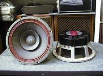
The transducers are vintage ones from Electro Voice. The tweeter is the "T350" and the bass-midrange the "SP12C".
for driving the SP12C the power amp is the NAD 2600.
That means, the preamp section of Cyrus V drives the internal power amp for tweeter and the external power amp for the SP12C.
This is already realized. But the external Cyrus V power supply and the increase of idle current has not yet been executed; I hope to get therefore a schematic from anyone. Maybe you know someone who can get this.
Attachments
Hi tiefbassuebertr,
I guess you could measure one with the PSX-R attached. That would give you more realistic numbers anyway, and also avoid typos in schematics. This is something I have suffered with from time to time.
No matter what my personal feelings are on your request, I am unable to grant your wish. Besides, I don't even have the Cyrus 5 manual. I didn't even know it existed. It probably came out in the time when Cyrus was not represented here. I'm going to bet it's very close to a 6 or 3i though. In some ways I hope you find the manual somewhere, but the thought also scares me a bit. While you may be good at what you do, and responsible at documenting changes, most techs are not either.
I do have to say, technicians will not self moderate their activities. They are generally a proud bunch, and the younger ones are convinced they know everything and perform their work to the highest standards. What a self-deluded lot (from what I have seen over many years). There doesn't seem to be any way to restrict service information to some responsible group either. It's in our nature to want to help others out. So, for some products, it is better to restrict the information. I hear the Sunfire guys will not allow outside service to occur in North America either. I'd say this is for good reason, since I was trained on the Lightstar product in the beginning. IF they released the schematics, I would expect mass destruction and possibly some dangerous situations as well. Actually, from experience I know this would happen.
Now, as for required amplifier power for tweeter use, half is fine. The power distribution in music for high frequencies is much lower than the bass demands. I do understand you really want to keep power dissipation similar as well.
-Chris
if the existing crossover already has the necessary components in it to ensure the audio signal gives the correct sound for the speaker then both sets of terminals expect to see the same signal voltage.
As an example let's take a simple single pole two way crossover with a frequency of 3kHz feeding two equal sensitivity drivers.
apply 1Vac @ 3kHz to both sets of bi-wireable terminals. the crossover sends half the signal to the lower driver and half the signal to the higher driver.
Now play an audio signal through that crossover speaker combination.
For equal sound from each of the drivers the crossover expects equal voltage on the terminals.
If you limit the voltage available from the upper amplifier, then the sound from the upper driver is also limited.
You are proposing just such an anomaly.
The crossover expects the same voltage drive at the terminals. If you reduce the amplifier supply voltage to half, you have effectively reduced the peak SPL of that driver by 6dB (quarter power = half voltage).
The HF transients will get clipped when trying to play at a vigorous SPL.
My recommendation is to feed all the drivers with the necessary signal voltage to allow all of them to reproduce the same maximum SPL that you have set as your target. Some go for 100dB other try for 110dB @ the listening position and a rare few try for 130dB @ 1m.
if the existing crossover already has the necessary components in it to ensure the audio signal gives the correct sound for the speaker then both sets of terminals expect to see the same signal voltage.
As an example let's take a simple single pole two way crossover with a frequency of 3kHz feeding two equal sensitivity drivers.
apply 1Vac @ 3kHz to both sets of bi-wireable terminals. the crossover sends half the signal to the lower driver and half the signal to the higher driver.
Now play an audio signal through that crossover speaker combination.
For equal sound from each of the drivers the crossover expects equal voltage on the terminals.
If you limit the voltage available from the upper amplifier, then the sound from the upper driver is also limited.
You are proposing just such an anomaly.
The crossover expects the same voltage drive at the terminals. If you reduce the amplifier supply voltage to half, you have effectively reduced the peak SPL of that driver by 6dB (quarter power = half voltage).
The HF transients will get clipped when trying to play at a vigorous SPL.
My recommendation is to feed all the drivers with the necessary signal voltage to allow all of them to reproduce the same maximum SPL that you have set as your target. Some go for 100dB other try for 110dB @ the listening position and a rare few try for 130dB @ 1m.
I don't understand this:
If you limit the voltage available from the upper amplifier, then the sound from the upper driver is also limited
Limited regarded the sonic quality? or limited regarded only the level?
All the other I know.
The royal way is still to match all function units individual.
I. e. complete crossover redesign, amplifier re-design and matching especially for the regarded transmission frequency range, introduce of level attenuators for each power amplifiers and level calibrate in such way, that I have still 6 db headroom to the distortion borderline at the max position of master level control
If there are the possibility of acoustical measurement, CAD simulation software for crossover networks and amplifiers (and sometimes hard to find amplifier schematics like that one of Cyrus V), this isn't a problem.
If there are not such things, I can only choice "plug and play"; that means in case of bi-amping identical power amps for each frequency rail cause it's identical voltage gain. At the same time this means only small steps in quality enhancement.
If there are schematics one of the other cyrus models above Cyrus III (see my post #1) it could be helpful, if the deviations are not too large to the model "Cyrus V".
Last edited:
limited regarding level. The upper range amplifier will clip 6dB lower than the mid range amplifier.I don't understand this:
If you limit the voltage available from the upper amplifier, then the sound from the upper driver is also limited
Limited regarded the sonic quality? or limited regarded only the level?
you have effectively reduced the peak SPL of that driver by 6dB (quarter power = half voltage).
Hi Andrew,
tiefbassuebertr's plan will work fine as long as the gain is the same (as noted), and the low frequency information is removed with a high pass filter before sending the signal to the amplifier first. Once the bass is gone, the peak voltages in the program material will be greatly reduced, allowing a lower powered amplifier to operate without clipping.
Hi tiefbassuebertr,
I am assuming this is a new design without a passive crossover network, the frequency dividing will occur in an active (electronic) crossover that lives between your preamp output and the input to the amplifiers.
-Chris
by the describted chain about post #12 in the moment a single ended amp (ZEN Var II) from an other guy is in use for the tweeter rail. But he want back his device as soon as possible.
What about the availibility of the schematic from the Cyrus V?
BTW - about
http://www.diyaudio.com/forums/solid-state/97117-cyrus3-experts.html
is a complete list with SMT codes and the real type number from various semiconductors
What about the availibility of the schematic from the Cyrus V?
BTW - about
http://www.diyaudio.com/forums/solid-state/97117-cyrus3-experts.html
is a complete list with SMT codes and the real type number from various semiconductors
Hi tiefbassuebertr,
I don't know how many different ways I can tell you that they will not release the service information. This applies to all their models, although some early schematics have found their way into the wild - from back when Mission owned the line.
The list of transistor markings to actual part numbers is nothing special, that stuff is freely available on most semi manufacturers web sites. So no flash of insight or special knowledge there.
Again, there are valid reasons for taking this course of action that was decided on from looking at the carnage left by the average service shop. I reluctantly agree with the decision as I would normally see no problem with service information being made available freely, or at reasonable cost. However, the point remains that they have excellent reasons for doing things the way they are, and that I have to agree with them.
I can see you've made this your mission in life. Oh well ....
-Chris
Now I can start the planning of project mentioned about post #12 because the complete CyrusIII schematic diagrams now online. There is a great similarity to the volume control section to Primare A20 and various Thule "Spirit" amps, but the input select was perform through relais and not CMOS ICs (HEF4066/4053) used by Primre and Thule. In new condition I would prefer relais, but I am not shure what is better after a certainly age.
Are there any news about schematics of the successor models later than Cyrus III?
Are there any news about schematics of the successor models later than Cyrus III?
Attachments
-
Cyrus-3power_l amp.pdf78.2 KB · Views: 696
-
Cyrus-3 control section.pdf94.2 KB · Views: 590
-
Cyrus-3phono amp.pdf69.1 KB · Views: 494
-
Cyrus-3pre amp.pdf90.9 KB · Views: 624
-
Cyrus-3power_r amp.pdf78.3 KB · Views: 601
-
Cyrus-3psu.pdf94.6 KB · Views: 566
-
Cyrus III MCU Zilog AN0220.pdf67 KB · Views: 550
-
Primare A20MKII-I20 EM1061-5 LM1972 Input sel.PDF79.1 KB · Views: 510
Last edited:
- Home
- Amplifiers
- Solid State
- Cyrus III power amp schematic here, but schematics of the later models wanted