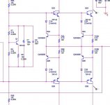
I'm using Anthony Holton's symmetrical amplifier which uses a BD139 in a Vbe multiplier circuit mounted on the heatsink with the IRF Mosfet output stage, to control the bias. I've noticed that this Vbe multiplier is really sensitive to temperature, so much so that blowing a little breeze over the heatsink causes a significant increase in bias; playing music reduces the bias significantly even though there is little change of heat (I have pretty large heatsinks that are barely warm). At least I won't have any thermal runaway problems, but I bet this hurts the sound quality.
Is there any way to modify the circuit to reduce the sensitivity of the bias circuit to temperature, so the bias remains steadier? There is a .47uf capacitor across the collector and emitter of the BD139, but I imagine increasing that value would only slow the rate of change of the bias, and not affect temperature sensitivity.
Thanks for your help. As you might have guessed, I'm a newbie.
This is absolutely normal with this circuit.
The speed of the bias regulation depends by the heating up, and cooling down speed of the BD139 on the heatsink. If You have big heatsink with large cross sectional area, the change will be slow. If You want to speed up the regulation, You can put the BD139 directly to the case of the output device.
You can increase the capacitor over the BD139, but I think it will do nothing with the regulation speed.
Sajti
If you are using a BJT as temp sensing element you will get more mv/deg than you need but you are also VERY sure not to get thermal runaway. You should use a mosfet instead. Mosfets have -8-10 mV/deg. Use any type in a case which you can attach. You can even use a small BS170 in TO-92 case and clue this thing to the heatsink. Not the you have to change resistor values a bit. Calculate for 2.5-3 V Vgs (instead of 0.6-0.7 for the bjt)
Hi All,
Thread's rather old, but as I came across this just now while designing a biasing for the output stage of a power amp I'm building, I'd like to share my finding on Vbe multiplier sensitivity.
Sensitivity of Vbe multiplier is defined as the change of the quiescent current of the output transistor stage with respect to change in temperature. When Vbe mult transistor is mounted on the heatsink where the output transistor is mounted (as it should be), the bias stability of the OPT will depend also on the Vbe mult transistor bias statbility.
Therefore, to change the sensitivity of the system, we can design the Vbe multiplier to have an emitter leg resistor, just like the normal emitter resistor stabilization technique. Increasing the emitter resistor value will decrease the sensitivity.
I didn't go into the math of the design, so I can't have formulas here.
In my design I use Orcad and on circuit simulation, Iq tends to go down with increasing temperature. The goal is to have no increase or decrease in Iq with temp changes.
I increased the Vbe mult transistor's emitter leg resistor until Iq flatlined.
Thanks All,
Dexter
Attachments
Hi,
The 2n3904's, along with the emitter resistors of TIP142/147, are used as active current limiters.
Aside from another important function when placing transistors in parallel, the emitter resistors translate the emitter currents of the TIP142's/147's into voltage. When the current increases such that the voltage drop across the resistors approaches 0.6~0.7V, the 2n3904's turn on and divert the base drive currents of the TIP's, rendering the output current limited.
Hi
From experience, the speed of thermal reaction of bjts reduced according to their Vce increasing. Maybe for this reason D.Self he is using a big Vce such MJE340 = 300V as Vbe multiplier (from memory, he doesn't explain why MJE340).
You are using a BD139; the BD137 is more faster and BD135 even much faster in thermal reaction.
Fotios
More junctions, using diodes in series will be more effective
When you heat a transistor it will give you a reduction of voltage drop that will reduce your stand by bias...but it is a single junction operating... so you have some percentual of decreasing.
When you install many diodes in series and put them touching the heatsink you gonna have, as result, added the reduction of resistances that is generated into each one of the diodes... when heated of course... this will allow you bigger control..bigger reduction of bias when hot... seems to me much better.... more reduction of resistance... a bigger percentual of action.
Other way is to use more than one transistor as heat sensor.
This is effectiveness, of course beeing effective we can call the thermal control a more sensitive too.
Into that sittuation effectiveness and sensitiveness goes confusing one each other, as they run together..when one increases the other increases too... a direct proportion.... direclty proportional
Carlos
i thought something like that also
uncle charly .....
lets suppose that you have one amp that has for example 2x 1943+ 2x5200 output stage, and then you design a vbe multiplier with a string of 4 diodes .....
would it be wise idea to make a pcb that could actually distribute the four diodes on a top of every power transistor ??????
what do you thing about that ????
many happy regards uncle charly !!!!!!
There are diodes in "transistor packages"
At least I know TO-220 diodes, 1-2 diodes in one TO-220.
But any transistor works as well as diode, with more possibilities for VBE multiplier.
The thing we want to use for output stage temp compensation
is to find semiconductor(s) with matching characteristic to the output transistors
when it comes to temperature.
And is a very good thing if they can easily be put onto the heatsink.
Close to them output transistors.
The connection between such a sensing semiconductor, diode or transistor, and the heatsink can be adjusted.
We can use something in between to reduce the temperature effect
and we can use very hard mounting pressure and tight connection to increase temp comp a bit.
hei line up
thanks for detailed explanation i think we are all familiar with all that but for example is not a good parctice if you have one amplifier with 2 pairs of 2SC5200-2SA1943 to use another 2 pairs for the vbe multiplier also .....may be is the best solution but not practik .....and for shure not effective ....thats why people use MJE 340 or BD 139 and so .....
and also your theory approach might be fine but doesnt answer my question ....
my question was:
in existing schematic that vbe multiplier is made by a string of 4 diodes would it be a nice to distribute them one per transitor output ?????
lineup said:.......The thing we want to use for output stage temp compensation
is to find semiconductor(s) with matching characteristic to the output transistors
when it comes to temperature......
Hi
I agree with this, but you have to keep in mind that the temperature characteristics of the Darlington pair is a product of the driver and output, not a sum, because they are both on the same die. This means it would be very difficult to match those characteristics of these outputs to a single Vbe multiplier transistor. You might be able to set a range that may overcompensate a bit and start with a higher initial bias. Or, you could use a Darlington for the Vbe multiplier, it might be closer.....or not. Yet another reason I'm not too keen on these devices as outputs, IMHO.
") I've repaired some old car amps with these in them and if I remember correctly, they used a Darlington TO-92 device as the Vbe multiplier.
I've repaired some old car amps with these in them and if I remember correctly, they used a Darlington TO-92 device as the Vbe multiplier.Well, the procedure of Iq adjusting may give some better answeers in the thread starter "Kilentra".
I reffer the method (it is the most common) that i use.
Also this procedure is reffered in an amplifier with tripple darlington output stage with 4 pairs of MJL2119X, and a BD137 as Vbe multiplier.
With the input shorted and the output open...
I place a DC voltmeter accross an emitter resistor (0,22Ù) and i start to adjust the Vbe trim-pot untill the voltmeter shows 11mV. That is a Iq = 50mA per output device, for an increased class AB operation (it is correct this deffinition?)
I attach a digital thermometer on the main heatsink to observe the temp. increation and to feel safe.
I leave the amp. to heated for 1 hour. Then, the voltmeter shows about 30mV==>Iq = 136mA, and the thermometer 55deg C.
I readjust the trim-pot to set back the Iq in 50mA. I observe now for half an hour the variations in Voltmeter and in thermometer. If all are OK and the Vbe mult. make his job well, then the voltmeter shows little variations from 10,5 to 11,5mV (thus Iq = 47,7 - 52,3mA) and the temp. remains stable at 45deg C about.
After this 1,5 hour procedure, i place the input signal (sinus sweep from 20 to 20000Hz) and the load in output, to obtain at least the half output power. When the temp. touches the 60deg C, then i disconnect everything and i wait to see if the Iq fall down to its original value, which happens usually in 3 to 4 minutes. After this the amplifier it is ready for use.
But...
When the adjusted and tested amp. is powered from cold, its Iq is arround 20mA and needs a good warming to obtain its original 50mA Iq and consequently its original class of operation.
Summarising, from my experiments, there is no fear of class reduction for a well warmed amplifier, because as i said above its Iq never falls down from 47mA.
For this reason, the constructors of super-dupper hi-end amplifiers, they suggest the preheat of device for one hour before listening (Uncle Charlie do you remember the ACA club of Greece? ).
As for the diodes, indeed it is a very good solution, but there is the need of matching them to have the same Iq from amplifier to amplifier. There is not the posibility of trimming such as with transistors. Peavey uses this scheme but with special selected double diodes MZ2361. If one of these two dual diodes failed, we are forced to replace also the two, with originals provided directly from the company.
I have checked the MJE340 instead BD137 in my projects, but proved very slow in thermal reaction. BD137 it is almost 4 times faster. I can't understand why D.Self he uses this beast of 300V as Vbe multiplier.
Hope to be helpfull.
Regs
Fotios
I reffer the method (it is the most common) that i use.
Also this procedure is reffered in an amplifier with tripple darlington output stage with 4 pairs of MJL2119X, and a BD137 as Vbe multiplier.
With the input shorted and the output open...
I place a DC voltmeter accross an emitter resistor (0,22Ù) and i start to adjust the Vbe trim-pot untill the voltmeter shows 11mV. That is a Iq = 50mA per output device, for an increased class AB operation (it is correct this deffinition?)
I attach a digital thermometer on the main heatsink to observe the temp. increation and to feel safe.
I leave the amp. to heated for 1 hour. Then, the voltmeter shows about 30mV==>Iq = 136mA, and the thermometer 55deg C.
I readjust the trim-pot to set back the Iq in 50mA. I observe now for half an hour the variations in Voltmeter and in thermometer. If all are OK and the Vbe mult. make his job well, then the voltmeter shows little variations from 10,5 to 11,5mV (thus Iq = 47,7 - 52,3mA) and the temp. remains stable at 45deg C about.
After this 1,5 hour procedure, i place the input signal (sinus sweep from 20 to 20000Hz) and the load in output, to obtain at least the half output power. When the temp. touches the 60deg C, then i disconnect everything and i wait to see if the Iq fall down to its original value, which happens usually in 3 to 4 minutes. After this the amplifier it is ready for use.
But...
When the adjusted and tested amp. is powered from cold, its Iq is arround 20mA and needs a good warming to obtain its original 50mA Iq and consequently its original class of operation.
Summarising, from my experiments, there is no fear of class reduction for a well warmed amplifier, because as i said above its Iq never falls down from 47mA.
For this reason, the constructors of super-dupper hi-end amplifiers, they suggest the preheat of device for one hour before listening
(Uncle Charlie do you remember the ACA club of Greece? ).As for the diodes, indeed it is a very good solution, but there is the need of matching them to have the same Iq from amplifier to amplifier. There is not the posibility of trimming such as with transistors. Peavey uses this scheme but with special selected double diodes MZ2361. If one of these two dual diodes failed, we are forced to replace also the two, with originals provided directly from the company.
I have checked the MJE340 instead BD137 in my projects, but proved very slow in thermal reaction. BD137 it is almost 4 times faster. I can't understand why D.Self he uses this beast of 300V as Vbe multiplier.
Hope to be helpfull.
Regs
Fotios
Re: i thought something like that also
Saki
If you have a good heatsink to mount your output transistors, then the thing is not so complex. You can mount the diodes as you wish, the difference in thermal reaction is negligible. I reffer again Peavey amps because are a good example:
As youknow probably, for easiness, Peavey uses seperate heatsinks for NPN and PNP output transistors. Thus the transistors are mounted directly on the heatsinks without insulators and the heatsinks are under the supply voltage. Now, to establish the Iq, it uses a string apparted from two dual MZ2361 and two 1N4003. The four diodes (actually six) are mounted through holes and thermal grease on heatsinks, one MZ2361 and one 1N4003 per heatsink. If Peavey amps have no problem (we know well this) of Vbe or Iq stability, then also you haven't problem i think.
Regs
Fotis
sakis said:uncle charly .....
lets suppose that you have one amp that has for example 2x 1943+ 2x5200 output stage, and then you design a vbe multiplier with a string of 4 diodes .....
would it be wise idea to make a pcb that could actually distribute the four diodes on a top of every power transistor ??????
what do you thing about that ????
many happy regards uncle charly !!!!!!
Saki
If you have a good heatsink to mount your output transistors, then the thing is not so complex. You can mount the diodes as you wish, the difference in thermal reaction is negligible. I reffer again Peavey amps because are a good example:
As youknow probably, for easiness, Peavey uses seperate heatsinks for NPN and PNP output transistors. Thus the transistors are mounted directly on the heatsinks without insulators and the heatsinks are under the supply voltage. Now, to establish the Iq, it uses a string apparted from two dual MZ2361 and two 1N4003. The four diodes (actually six) are mounted through holes and thermal grease on heatsinks, one MZ2361 and one 1N4003 per heatsink. If Peavey amps have no problem (we know well this) of Vbe or Iq stability, then also you haven't problem i think.
Regs
Fotis
Hi All,
Since there is almost infinite number of combinations possible for what OP and Vbe multiplier transistors to use during design, a designer is faced with the task of simplifying the design by making circuit bias less dependent on device characteristics across an operating variable, say, temperature, like the original problem question. It also simplifies part replacement, as the design will not be so "much" dependent on device parameters, to some degree.
The solution of placing an emitter resistor in the Vbe mult transistor will correct the quiescent current drift vs temperature of the system.
You can simulate the design or an existing circuit using DC sweep analysis. Then monitor Icq, sweep variable would be temperature. You can see that for certain values of Re placed on the emitter leg of Vbe mult Q, the change of Icq vs temp would be minimal.
Thanks,
Dexter
Hmmm....
By looking at the schematic of a CS-1000 most carefully, i can see a 120Ù resistor connected in parallel with the last down 1N4003 diode (which of the cathode it is connected at the base of the negative predriver)... probably it plays the same role as the emitter resistor that you propose, and which is a good improvement... even if i had no problem with thermal compensation issues... but this is related also with CCS...
in any case,
thanks Dexter for this information. Probably it is precious for some designs.
Regs
Fotios
thanks fotios
( nice to see you )
my idea was originally motivated from having one amp with 4transistors in the output made with a string of 4 diodes for the VBE .... eventhough heat sink might be good and enough for the application there is a very good chance that transistors might heat up with a small diference depending on load, pcb,emmiter resistors ,matching, and many others ( thats why i think you have thermal track transistors )
so lets suppose that between the 4 transistors one is drifting probably forcing the heatsink to warm up and so on if the diode is attached directly to one transistor will probably prevent this from happenig ....
is that good practice ??? or the diference might occure in temperature is too small to bother????
Re: thanks fotios
Thanks Saki for the welcome
Your description it is more comprehensible this time. I think your thought is right. Suppose it comes from OnSemi thermal track transistors in which there is no need for matching. You have also the posibility of use the same practice as Peavey... thus you can omit the tiring work of insulating by using seperate heatsinks (the only you have to make is the cutting of heatsink in two halves) to mount the NPN and PNP drivers and output transistors.
Make an experiment.
Regs
Fotis
sakis said:( nice to see you )
my idea was originally motivated from having one amp with 4transistors in the output made with a string of 4 diodes for the VBE .... eventhough heat sink might be good and enough for the application there is a very good chance that transistors might heat up with a small diference depending on load, pcb,emmiter resistors ,matching, and many others ( thats why i think you have thermal track transistors )
so lets suppose that between the 4 transistors one is drifting probably forcing the heatsink to warm up and so on if the diode is attached directly to one transistor will probably prevent this from happenig ....
is that good practice ??? or the diference might occure in temperature is too small to bother????
Thanks Saki for the welcome
Your description it is more comprehensible this time. I think your thought is right. Suppose it comes from OnSemi thermal track transistors in which there is no need for matching. You have also the posibility of use the same practice as Peavey... thus you can omit the tiring work of insulating by using seperate heatsinks (the only you have to make is the cutting of heatsink in two halves) to mount the NPN and PNP drivers and output transistors.
Make an experiment.
Regs
Fotis
- Status
- This old topic is closed. If you want to reopen this topic, contact a moderator using the "Report Post" button.
- Home
- Amplifiers
- Solid State
- Vbe multiplier sensitivity