Mr. Wayne, how low impedance do you have really?
The waveform of the current is short spikes which creates over tones the mains and they may interfere with other apparatus connected to the mains. Your rectifier bridge will have a harder life and also the transformer. The VA rating becomes half the value if you have a huge capacitor battery. A 500VA transformer can only take 250 VA if you have a PSU like this.
Hello ,
Thanks for the explanation , i was not aware of losing 50% of my transformer rating , why would this be so ? The bridge rectifier is rated @ 30 amps.
Originally posted by a.wayne
You suggest increasing the resistor value to as much as 33 ohm from 4.7?
I had thought about upping it to a 30 watt , so i will now consider a higher imp by using a 33 ohm do you think the rest of the circuit will be sufficient ?
I do not have a clamp meter , so I'm not able to adjust as you suggest and was going to increase the resistor to 12ohm/30 watt .. do you still suggest 33 ohm ?
Yes, 33 ohms/30W should do. As long as the delay is about 1/2sec, you'll be fine.
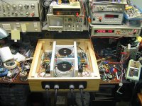
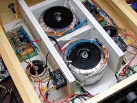
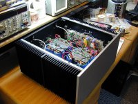
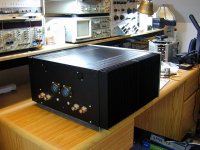
I've just finished a Dual Mono a month ago. Power Transformers are external with their associated Inrush circuitry. Each channel is powered by a 800VA transformer with 88,000uF/100V of filter caps. Electrically, the 2 channels are isolated.
I used a small transformer for the Inrush. It also provides 12V regulated DC for the 12V Panel switch and powers a tiny extractor fan at the back panel. The 12Vdc front panel switch activates a High Current (30A) Relay which is wired to the incoming Mains fuse. This relay acts as the Main power switch. The front panel switch is a trigger. Safer (low voltage) and much Prettier (with illuminated LED).
You can see the metal clad resistor on the Inrush PCB. It is a 39 ohms/30W.
Mike
Attachments
The losses is I*I*R and if the peaks go really high then you'll get high peak power in losses but the thing is that the VA rating is only valid for a resistive load and when you add so much capacitance you will also generate lots of reactive power distributed in a wide spectrum.Hello ,
Thanks for the explanation , i was not aware of losing 50% of my transformer rating , why would this be so ? The bridge rectifier is rated @ 30 amps.
Your simply sim. predicts there will be an improvement in transient response..
The point is that with rails of +/- X, you shouldn't expect the output to swing to +/- X. For real music, X-7 is probably the limit. For full power bench testing, X-15 or X-20.
More capacitance will get you to maybe X-5 for real music, that it isn't an effective way to get a few extra volts of output swing. It won't help at all for sine wave bench testing.
The diodes are only forward biased for a very small part of the AC cycle, and the current pulses to top up the caps are at 120Hz. You have to consider whether there is any upstream current limitation (such as the transformer) which would mean that the additional capacitance may not do any good at all for an extended high power load.
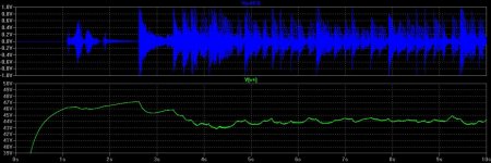
Here's another simulation result where the load applied is real music, full power into 4 ohms. Top trace (blue) is the music waveform, bottom trace (green) is the PS rail with 70000uF.
Basically, if you're playing real music at realistic levels, the PS capacitance you have now should be more than enough to handle any transients. You could argue that the additional capacitance would result in a lower ESR and therefore higher current delivery for transients, but it would likely be masked by the effective output impedance of the output transistors and the emitter resistors.
If you want to do the experiment, please let us know the results. But as I and others have said, you need to look at all the upstream components to make sure they can handle the increased inrush current.
Attachments
Rather than a resistor how about to CL-60 thermisters? These start at 10 ohms and dcrease as the current flowing through them heats them up. They can take a few amps. I use 2 in series with my Krell clone and it works well. And you wont blow them up if you use a variac because they can handle the current.
Rather than a resistor how about to CL-60 thermisters?
That's what I use.
Complete soft start:

Warning: R6 very close to the chassis!
Not as close as it seems. Besides, it is just 12V there - power for the relay.
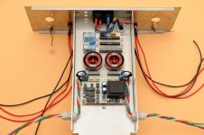
Here is all, what you need - inrush resistors ( and PTC ), bypassed by 16A relay, controlling switch on/off logic, mains filters, remote control for cascade switching of next equipments connected in chain...unit is usable for 100-2000 VA transformers ( by 230 V AC )....
Attachments
Aha, I thought it was at the primary side which is the usual approach.
It is powered from the supply that it is current limiting, shunting V+ down to 12V to close the relay after a one second delay. The safest, most efficient approach I think as the thermistor can easily carry the full load if the relay fails (or if the relay fails to close).
I've used power resistors before with an auxiliary transformer to power the soft start but that's like "stone age" compared to this.
Yes, 33 ohms/30W should do. As long as the delay is about 1/2sec, you'll be fine.
I've just finished a Dual Mono a month ago. Power Transformers are external with their associated Inrush circuitry. Each channel is powered by a 800VA transformer with 88,000uF/100V of filter caps. Electrically, the 2 channels are isolated.
I used a small transformer for the Inrush. It also provides 12V regulated DC for the 12V Panel switch and powers a tiny extractor fan at the back panel. The 12Vdc front panel switch activates a High Current (30A) Relay which is wired to the incoming Mains fuse. This relay acts as the Main power switch. The front panel switch is a trigger. Safer (low voltage) and much Prettier (with illuminated LED).
You can see the metal clad resistor on the Inrush PCB. It is a 39 ohms/30W.
Mike
Hello Mike ,
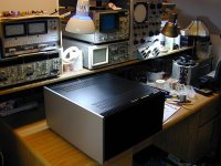
Nice piece of kit , Love the chassis and the tranny isolation is the way to go.
What design is the amplifier based on ? .
The losses is I*I*R and if the peaks go really high then you'll get high peak power in losses but the thing is that the VA rating is only valid for a resistive load and when you add so much capacitance you will also generate lots of reactive power distributed in a wide spectrum.
Hello PA,
I'm at a lost here as i cannot technically dispute what you are saying , i can only recount my practical experiences and have found that consistent 2 ohm operation requires more capacitance than one would use in a 8 ohm operation amplifier.
My question would be , how much is 2 much and how much is enuff .
1. Is 20,000 enuff ? what about 100,000 ....
2. Why not do it electronically ,applying just what is necessary for the load. ? based on your explanation, electronic regulation would seem like the only way to go ..
3. The supply voltage is very important and without a perfect supply wouldn't added capacitance make a difference ?
4. What would be your choice for low impedance operation , what would be the max uf you would run ?
The point is that with rails of +/- X, you shouldn't expect the output to swing to +/- X. For real music, X-7 is probably the limit. For full power bench testing, X-15 or X-20.
More capacitance will get you to maybe X-5 for real music, that it isn't an effective way to get a few extra volts of output swing. It won't help at all for sine wave bench testing.
The diodes are only forward biased for a very small part of the AC cycle, and the current pulses to top up the caps are at 120Hz. You have to consider whether there is any upstream current limitation (such as the transformer) which would mean that the additional capacitance may not do any good at all for an extended high power load.
Here's another simulation result where the load applied is real music, full power into 4 ohms. Top trace (blue) is the music waveform, bottom trace (green) is the PS rail with 70000uF.
Basically, if you're playing real music at realistic levels, the PS capacitance you have now should be more than enough to handle any transients. You could argue that the additional capacitance would result in a lower ESR and therefore higher current delivery for transients, but it would likely be masked by the effective output impedance of the output transistors and the emitter resistors.
If you want to do the experiment, please let us know the results. But as I and others have said, you need to look at all the upstream components to make sure they can handle the increased inrush current.
Would love to see your simulation @ 2 ohm and 200K vs 70 K ..
25 years ago when doing club pro sound, Bryston supplied us with amplifiers , which were being operated @ 2 ohm . I had requested to add more caps and they advised against it , very much so. Prior to this we were using Dynaco 416's with there C100 added capacitor bank , no issues .
Well we ended up having to send the Brystons back every 2 yrs for re-capping as they would start to get noisy and of course with there great warranty , it was done free of charge . send amp to Bryston , re-cap , play again repeat ...
Historically over the years for me , a large bank of caps for low impedance operation makes a difference , maybe 220K is over board , but 70 K is 2 small for such low power operation in my books and currently anything over 50 -70 watts now and my amp takes on a grungy sound and get harsh , same as the Brystons, they did when they needed re-capping ..
Rather than a resistor how about to CL-60 thermisters? These start at 10 ohms and dcrease as the current flowing through them heats them up. They can take a few amps. I use 2 in series with my Krell clone and it works well. And you wont blow them up if you use a variac because they can handle the current.
The amplifier already has a soft start circuit , just wanting to make it safe for the extra load ..
Last edited:
Hi,
this was posted in the Forum a few times. It made a bit more sense than what I had done previously with my power amps and so I adopted it.
I have never been able to fault it since, other than putting up with a lot of flak from disbelievers among the Membership.
Set the input filters' F-3dB about a decade wider than the frequencies you want to reproduce.
Set the NFB filter more than half an octave lower than the high pass input filter.
Set the PSU RC more than half octave below the NFB filter.
I set any pre-amp's filters a further half octave to one octave wider than the power amp's.
eg.
20Hz to 20kHz audio frequency range.
input filters set to <=2Hz and >=200kHz, i.e HP RC>=80ms & LP RC<=800us
NFB RC >114ms
PSU RC >114*1.414, i.e. >162ms
For 8ohm speakers this 20Hz requirement becomes >+-20mF/ch
for 4ohm >+-40mF/ch
for 2ohm >+-80mF/ch
Hi,
this was posted in the Forum a few times. It made a bit more sense than what I had done previously with my power amps and so I adopted it.
I have never been able to fault it since, other than putting up with a lot of flak from disbelievers among the Membership.
Set the input filters' F-3dB about a decade wider than the frequencies you want to reproduce.
Set the NFB filter more than half an octave lower than the high pass input filter.
Set the PSU RC more than half octave below the NFB filter.
I set any pre-amp's filters a further half octave to one octave wider than the power amp's.
eg.
20Hz to 20kHz audio frequency range.
input filters set to <=2Hz and >=200kHz, i.e HP RC>=80ms & LP RC<=800us
NFB RC >114ms
PSU RC >114*1.414, i.e. >162ms
For 8ohm speakers this 20Hz requirement becomes >+-20mF/ch
for 4ohm >+-40mF/ch
for 2ohm >+-80mF/ch
Andrew ,
Huh!
Way above me there Buddy , i will have to wait for PA and others to layman it a bit for me .
a.wayne,
let me know the rail voltage and the max output current and I'll look at it tonight.
80v at the caps , trans are rated @ 1800va ( 15A)
80v at the caps , trans are rated @ 1800va ( 15A)
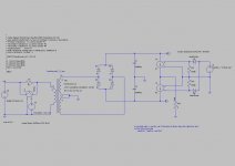
Ok first a description of the modeling approach and then some results. See the attached schematic.
The AC line is an ideal voltage source sine wave 170V p-p. Inrush protection is 4R7 bypassed with a relay modeled using an ideal switch that turns on after 2 sec.
The transformer is 3 inductors, with a coupling factor of 0.98 between them. See the .subckt in the schematic. The ratios of the inductances are set to get the proper output voltage, series resistances are a guess. I don't know if the values for L1, R1, R2, R3 are realistic, I'd appreciate any guidance. I haven't been able to find any transformer manufacturers who spec those parameters. Diode bridge is just the default diode model, same for the caps.
The output stage is modeled using a voltage source, splitting it into + and - halves using ideal diode primitives, and driving ideal voltage controlled current sources. For these sims I set the gain to 16, i.e. 1V input -> 16A current into 4 ohms, to swing 64V max or 80% of the rail voltage. The cool thing is you can drive the voltage source with a .wav file. (I used "Return from Planet Egalica" by Dubblestandart, for anyone who's wondering.)
I won't claim that this model is 100% accurate, but I think it is good enough to get a detailed understanding of the problem. It can be easily modified to use models of the the actual diodes, multiple caps and their ESR, etc.
Attachments
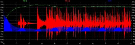
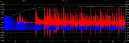
Here's two waveforms showing the rail voltage, the voltage waveform at the load, and the current in one of the diode bridge diodes for 70,000uF and 200,000uF.
In both cases the rail sags to about 60V. It never gets charged all the way to 80V because I haven't come up with a way to delay the start of the .wav file. But if there was excess current capacity upstream from the caps, it would get there. In any case, with 200,000uF the rail is a little smoother vs. 70,000uF but it still sags to about the same point, and the diode current "in use" is about the same.
So this supports my earlier contention that additional capacitance, beyond "enough", doesn't do any good. Unless you're listening to recordings with very high peak to average ratios, maybe the 1812 Overture with real howitzers.
Attachments
Last edited:
Ok first a description of the modeling approach and then some results. See the attached schematic.
The AC line is an ideal voltage source sine wave 170V p-p. Inrush protection is 4R7 bypassed with a relay modeled using an ideal switch that turns on after 2 sec.
The transformer is 3 inductors, with a coupling factor of 0.98 between them. See the .subckt in the schematic. The ratios of the inductances are set to get the proper output voltage, series resistances are a guess. I don't know if the values for L1, R1, R2, R3 are realistic, I'd appreciate any guidance. I haven't been able to find any transformer manufacturers who spec those parameters. Diode bridge is just the default diode model, same for the caps.
The output stage is modeled using a voltage source, splitting it into + and - halves using ideal diode primitives, and driving ideal voltage controlled current sources. For these sims I set the gain to 16, i.e. 1V input -> 16A current into 4 ohms, to swing 64V max or 80% of the rail voltage. The cool thing is you can drive the voltage source with a .wav file. (I used "Return from Planet Egalica" by Dubblestandart, for anyone who's wondering.)
I won't claim that this model is 100% accurate, but I think it is good enough to get a detailed understanding of the problem. It can be easily modified to use models of the the actual diodes, multiple caps and their ESR, etc.
Half the capacitance in your SIM, it is 200K total not 200K /side ......
I should have the necessary parts for the soft start next week and then i will proceed to first test the new caps and then with all 4 caps for a total of 220K...
I have noticed that different brands sound different , so first is to see if there is any degradation in the sound with the new type ( Brand) first with the same capacitance , then upping ...
Viewing your results, there is a big difference for the first 4 secs. Then less so afterwords, the ripple is much smoother , now to see if we can hear the difference on some 1812 dubwise..
thanks MightyDub ..
Last edited:
Half the capacitance in your SIM, it is 200K total not 200K /side ......
Ah, that changes things. It looks like 35K/side is "enough" for 8 ohm loads driven to about 80% of the rail, for 4 ohm loads it needs more and not surprisingly 70K looks good. But you'll have to turn it WAY up to get the benefit... hope the spouse / neighbors are understanding.
...now to see if we can hear the difference on some 1812 dubwise..

- Status
- This old topic is closed. If you want to reopen this topic, contact a moderator using the "Report Post" button.
- Home
- Amplifiers
- Solid State
- Soft start question