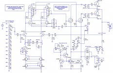
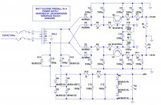
Thank you for the very motivating event this year. For those of you who saw and heard the Watt Sucking Fireball No.4, and asked for a discussion of the circuits, here is the schematic for the power supply and one channel of the Amp. It is a simple application of J-Fets in a minimized gain chain of linear gain stages. An input stage that I call a differential-cascode-transimpedance amp is used to generate the initial amplification and convert the single ended input to a full differential drive that continues through to the P-P output stage. Being new to this forum, let me know if the Schematics didn't attach and help me out. More on this will follow if wanted.
Kirkwood
Kirkwood
Attachments
Parts, Parts and more Parts
There are those things that a DIY will always need as I did for this project. Since this project was a High speed path from a clean piece of paper to the demonstrable show unit, Parts and Parts quick were needed. If any of you are in the Bay area, one of the great surplus parts sellers is in Milpitas. The EXCESS SOLUTIONS company www.excesssolutions.com Excess Solutions was essential to the successful completion of this amplifier, from toroidal transformer, speaker terminations, RCA jacks, heatsinks, resistors, caps, and wire all were from the Excess guys. They really have it all and my thanks to Mike, Todd and AJ for running the ultimate house of parts and for just being there or this project would have taken much longer.
There are those things that a DIY will always need as I did for this project. Since this project was a High speed path from a clean piece of paper to the demonstrable show unit, Parts and Parts quick were needed. If any of you are in the Bay area, one of the great surplus parts sellers is in Milpitas. The EXCESS SOLUTIONS company www.excesssolutions.com Excess Solutions was essential to the successful completion of this amplifier, from toroidal transformer, speaker terminations, RCA jacks, heatsinks, resistors, caps, and wire all were from the Excess guys. They really have it all and my thanks to Mike, Todd and AJ for running the ultimate house of parts and for just being there or this project would have taken much longer.
Attachments
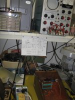
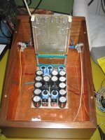
some mess before the event
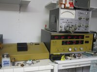
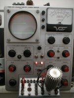
Thanks for sharing the design! Looks like you have some really nice test gears. That Tektronix 570 curve tracer certainly looks great. And the ther box is some kind of semiconductor noise analyzer?
Thank you for the very motivating event this year. For those of you who saw and heard the Watt Sucking Fireball No.4, and asked for a discussion of the circuits, here is the schematic for the power supply and one channel of the Amp. It is a simple application of J-Fets in a minimized gain chain of linear gain stages. An input stage that I call a differential-cascode-transimpedance amp is used to generate the initial amplification and convert the single ended input to a full differential drive that continues through to the P-P output stage. Being new to this forum, let me know if the Schematics didn't attach and help me out. More on this will follow if wanted.
Kirkwood
Nice trick to get that -45VDC. Not many here would remember how to do that, I suspect. It does date you
") . And me.
. And me.Anyway, enjoyed our chat at BA.
Jan Didden
Linear Audio
Well..........
The Quan-Tech was used extensively to match the gain, IDss/Vgs and noise characteristics of Linear Sys parts used in the BAF demo amp. Some years ago I worked with Mr. Stansbury to refine a vacuum tube adaptor for the 5173 to also measure equivalent input noise of small signal triodes. The WattSuckingFireball4 can be operated without feedback and have only the gain shift over temperature. Distortion and IM are about the same over the audio passband of 20-20K. Linearity was a combination of carefully matched parts, including resistors and caps, but primarily established by the balanced signal path Gm and successive reverse impedance isolation from stage to stage by strict differential device matching, optimized bias centering, and massive differences in source to load impedance.
The Tek 570 is my best tool for matching up transfer functions of various triodes used in tube preamps designed here. Another tool that has provided a great amount of data is the General Radio 561-D Vacuum Tube bridge designed by Tuttle which produces remarkably accurate Gm, Rp, and mu numbers for all the operating bias points of a thermionic triode or J-Fet at various audio frequencies.
K-wood
Last edited:
WSF continues
Life on the Bench
There are 3 fundamental principles in this amp design. Linearity, elimination of DC gain terms, and stage gain consistency. A review of all gain elements from the first Thermionic Triode to a FET (conceived before bipolars by Shockley) to bipolar transistors, mosfets, depletion mode or enhancement, IGBT's etc., show a progression of greater gain and greater nonlinearity over time . The nonlinearities are many and varied from square law to exponential with complex biasing variations from current crowding to beta shifting over collector current and reverse feedback differences with gain/impedance changes over the operating range of use. A careful review of any gain element's transfer function will reveal operating regions to use and to avoid. Personally I prefer low mu triodes as the Avatar shows. The WSF input stage is at first, a simple differential pair of J-Fets, but only at AC voltages above the passband of a coupling R-C network between the sources. This eliminates DC offset terms and drift of a normal differential amp while allowing independent manipulation of biasing conditions. This comes in handy later in the output circuit. Differential J-Fet pair sources fed from a resistance to some minus supply will not perform well in either common mode rejection or single ended to differential conversion because there will always be a difference in source current produced from the driven and undriven input gate voltage. A dual tracking current source was used here employing a low noise LSK170 as the (I) source and a pair of low noise dual NPN’s configured as a full Wilson Mirror. Keeping the design simple, there are no cross coupled things going on but the need to keep miller effects negligible dictates a cascode loading of the Diff input pair. By stacking a pair of fets as a GM amp and feeding back a 10K ohm resistor to the GM amp gate, we can produce an amp stage with about 46 db of open loop gain and feed the Diff amp drains into a virtual ground node at the input connection of a 10K GM feedback resistor. The 1 ma drain current biases up 10 volts across the 10K and swings it's output side to the change in diff current times the 10K resistor while holding the Diff stage drains to about 1/200th of the output voltage swing. Now we have a single ended to differential non inverting voltage gain and a bandwidth of about 1 MHz. Driver output Z is about 50 ohms…..More through the looking glass later.
Kirkwood
Last edited:
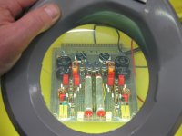
The driver transistors were ones that I made 16 years ago...
Good lord! Talk about DIY.


Good lord! Talk about DIY.
Timbering BA-traveller,
Not DIY, Kirkwood the apparant Harley afficinado is Mr KRL.
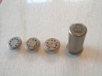
His TO-8 metal can FET tubes were predecessed by Teledyne stuff, though those were cascoded high voltage JFET devices with a pentode signature.
Your memory is good Cricket
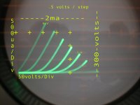
Here's the original 0AX7 assy and a 7027-A silicon tube emulator on the curve tracer
Timbering BA-traveller,
Not DIY, Kirkwood the apparant Harley afficinado is Mr KRL.
His TO-8 metal can FET tubes were predecessed by Teledyne stuff, though those were cascoded high voltage JFET devices with a pentode signature.
Here's the original 0AX7 assy and a 7027-A silicon tube emulator on the curve tracer
Attachments
Hi roadbagger,
Are you sure you guys want to associate with this much retro technology? I still have 1000's of JFETS from the old Micropower fab circa 1977 (John Hall and company). I don't see a profitable future in this direction. It's fun and all that, but the applications are falling to cheap CMOS techniques every day.
BTW one of my cousins was married to John Davidson. He came to a funeral in a Hummer painted green and gold (The Pack) with 4 chesse heads in every corner.
Last edited:
Ya-Know.........
Hi roadbagger,
Are you sure you guys want to associate with this much retro technology? I still have 1000's of JFETS from the old Micropower fab circa 1977 (John Hall and company). I don't see a profitable future in this direction. It's fun and all that, but the applications are falling to cheap CMOS techniques every day.
QUOTE]
Sorry fella, but there is always the transition between electricity and the sound making things we love to emulate sonic reality with and that zone is my life's passion, and it's all linear. I've got a trove of the MP parts too and the ones that John is making now, I prefer. Linear Technology does improve with science and the LIS guys are about to make our linear, low IM lives a lot better. "loop gain is cheap" (John G.) but it sure doesn't sound good.
K-wood
Ok go for it, hobby businesses are at least fun.
- Status
- This old topic is closed. If you want to reopen this topic, contact a moderator using the "Report Post" button.
- Home
- Amplifiers
- Solid State
- Watt Sucking Fireball Series