Hello airbody!
Some peeps has already post similaire or same problem but I have yet to see a solution. The fused resistors (R401 and R402) has been changed so that is not the reason.
The amp wont go out of protection mode (red light instead of green as it should be).
I saw that the NAD 370 often has a similair problem that is resolved by changing the electic capacitors in the protection circuit.
Maybee somebody could help me find that circuit in the NAD c350, already that would be a huge help. Even the service manual for the C350 doesnt seem to specify where this module is. I've might found it but I'm not sure.
What else could be the reason? Theoreticly. What could I do to advance in this frustrating enterprise?
Thank you in advance for your thoughts on this,
Best regards,
Erik
The protection module is IC105, type UPC1237H. From the schematic it appears to be on the main board.
If you have DC offset at the amp output the protection circuit is working as it should. You might need a scope to watch the output to see if it shows a DC voltage at power on.
If you have DC offset at the amp output the protection circuit is working as it should. You might need a scope to watch the output to see if it shows a DC voltage at power on.
Seems like we have a really difficult one on our hands.
I have yet to read about ONE single DIYer on the wwooooole internet who have resovled this one except Burbank who sais that sometimes it's the C143. And offcourse R401, R402 who on old models was not already replaced by NAD.
Man, I'm dying here. So typical that people all over with the C370 solves this one so easy but for the C350 its a hard nut to crack.
I'm thinking total recap now, despertly. By the way, how do one test caps to see if one should indeed replace the same?
Cheers
The service manuals for the C350 and C320BEE both indicate that the DC offset voltage at the speaker terminals should be less than 0.03 VDC. There are separate adjustments for the left and right channels and the reading is taken with no load connected to the speaker terminals.
What are you using to measure the voltage and do you have a load connected? Do both the left and right channels read the same DC voltage at the speaker terminals?
For the C350, if the protection circuit is activated, a relay should open the connection to the speaker terminals and you should read zero volts.
I would locate the datasheet for the UPC1237H and study it to determine what the voltages at each pin should be. Then measure the voltages at the UPC1237H pins in the C350 to find out what is activating the protection circuit.
well that is whack, how can I have voltage at speaker outputs then? To answer your questions, yes same on both channels. And I am using a multimeter set on DC. No load connected.
Im waiting for a ESR meter. I will check all the caps with it. If that does not indicate something is a miss, I'll get deep into that circuit but at the moment I'm just hoping my new ESR meter will find a bad cap somewhere, maybee it's too much to hope for though.
Im waiting for a ESR meter. I will check all the caps with it. If that does not indicate something is a miss, I'll get deep into that circuit but at the moment I'm just hoping my new ESR meter will find a bad cap somewhere, maybee it's too much to hope for though.
SOLVED!!
Finally, pheuw!
I ordered an ESR meter from this east european dude. Best buy I have ever made. He only wanted like 35 bucks for it and this means it has already payed for itself since I now fixed the C350 with it.
I quickly measured all the caps in the amp. And I had FOUR open caps. Two of them was in my protection circuit. Anyways it cost me 2 bucks for the caps and 30 minutes of work now it has bumped the C320BEE that was stinkin' up the place (nah it's alright).
For me it was C119, C145, C155 and C159 that was open. But I would have put in a lot of time checking if not for the ESR meter. Testing caps IN circuit is clearly the way to go.
Cherio

Sorry for kicking this topic, but I would like to thank hostarn very much. I have had a defective C350. The front panel did not work properly and did not get any power. So I was unable to change the input mode. I've just repaired this nice amplifier by replacing the fusible resistors (R401 and R402) hostarn wrote earlier about. I did not know that failure of these resistors is a common defect ") .
.
.Another defective C350..
Hello, I thought I might as well continue this old thread, as I have a similar issue with a C350.
I bought it cheap as defective a while back. The protection light would come on, and stay on - same as many others have experienced. I have tried to fix it, but I'm stuck now, and would really appreciate a little help
Full schematics are attached as PDF.
So far I have:
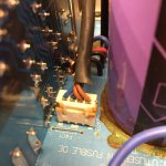
Replaced the two fusible resistors (they were both open!) with solid wire jumpers, as has been recommended elsewhere.
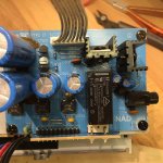
Checked all capacitors in circuit with ESR Micro 4.0 (the russian one), which seems to be quite reliable for this purpose. I didn't find any open caps, but some of the "known suspects" in protection circuit had very high ESR (like 6r) and low capacitance. So I replaced most of these for good measure (C135, C149, C159, C160 and others). The C143 measured perfectly in my case (also out of circuit), so I put it back in.
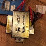
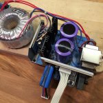
After these changes, I powered it up using my 100w bulb tester. The result is a steady bright flashing of the bulb, with about 1 second intervals. At the same time, relay RL501 clicks on and off. After leaving it like this for about 8 seconds (longest I dared..), the secondary transformer TR02 had a slight burned smell, and felt warm to the touch.
Having seen somewhere (on Youtube I think), that shorted TR02 is a common problem, I took it out of circuit, and measured the voltages. It has dual secondary windings. The blue pair gives 19 VAC and the brown 9 VAC, which sounds ok, as they are used for 12v and 5,6v output. The clicking relay RL501 looks to in the 12v circuit, but can't seem to find it on schematics - I think it is lost in the page break.
Measured resistance between primary wires:
Black-brown: 177r
Black-red: 0,52k
Red-brown: 348r
Measured resistance between seconday wires:
Blue-blue: circuit
Brown-brown: circuit
Blue-brown: open
Seems like reasonable values to me, but could it still be defective?
And if not, what to do now?
PS. If repair is unsuccesful, it is no big loss: Mainly trying to fix it for the practice, and it really is a crappy cheap construction - with power wires left chafing on sharp metal edges etc.. . A bit of pain to disassemble also, not a well thought out design.
Hello, I thought I might as well continue this old thread, as I have a similar issue with a C350.
I bought it cheap as defective a while back. The protection light would come on, and stay on - same as many others have experienced. I have tried to fix it, but I'm stuck now, and would really appreciate a little help
Full schematics are attached as PDF.
So far I have:
Replaced the two fusible resistors (they were both open!) with solid wire jumpers, as has been recommended elsewhere.
Checked all capacitors in circuit with ESR Micro 4.0 (the russian one), which seems to be quite reliable for this purpose. I didn't find any open caps, but some of the "known suspects" in protection circuit had very high ESR (like 6r) and low capacitance. So I replaced most of these for good measure (C135, C149, C159, C160 and others). The C143 measured perfectly in my case (also out of circuit), so I put it back in.
After these changes, I powered it up using my 100w bulb tester. The result is a steady bright flashing of the bulb, with about 1 second intervals. At the same time, relay RL501 clicks on and off. After leaving it like this for about 8 seconds (longest I dared..), the secondary transformer TR02 had a slight burned smell, and felt warm to the touch.
Having seen somewhere (on Youtube I think), that shorted TR02 is a common problem, I took it out of circuit, and measured the voltages. It has dual secondary windings. The blue pair gives 19 VAC and the brown 9 VAC, which sounds ok, as they are used for 12v and 5,6v output. The clicking relay RL501 looks to in the 12v circuit, but can't seem to find it on schematics - I think it is lost in the page break.
Measured resistance between primary wires:
Black-brown: 177r
Black-red: 0,52k
Red-brown: 348r
Measured resistance between seconday wires:
Blue-blue: circuit
Brown-brown: circuit
Blue-brown: open
Seems like reasonable values to me, but could it still be defective?
And if not, what to do now?
PS. If repair is unsuccesful, it is no big loss: Mainly trying to fix it for the practice, and it really is a crappy cheap construction - with power wires left chafing on sharp metal edges etc..
. A bit of pain to disassemble also, not a well thought out design.Attachments
- Status
- This old topic is closed. If you want to reopen this topic, contact a moderator using the "Report Post" button.
- Home
- Amplifiers
- Solid State
- NAD c350 protection module problem