Hey PB2:
I almost forgot this thread, and dang it I have not yet pulled out the amp at all.
I worked on several of these in the late 70's and early 80's, still own one, but got tired of replacing the outputs and drivers, so went tube. Great case for a build, good metering circuit with some additional filtering.
Ill try to find my notes from back then and see if there are any thoughts I had then on these puppies.
Keep us posted JBLMAR on the repair you get in, fun and interesting it could be..
Harlan
Hey Ron, Aaron told me he met you yesterday. Good luck with the 250M. I have the 240 manual I downloaded off HIFIENGINE. It is identical to the 250M except no meters. They don't have the 250M manual. They do have a 250, but it is different somewhat by what I understand. Chuck
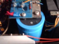
Did a visual on the right amp board. Marantz didn't mark componet reference numbers on the board. Big mistake.
I checked the resistance value of the burned resistor since one side was not burned. 39 ohms, 1 watt. Either R529 or R530. I'll check the polarity of Q510/11 to be certain.
Either way, it goes to Q510 or Q511, the NLA To-66. They measure Ok. That's good.
R529/30 then leads to the output transistors. All 4 are shorted.
BTW. The output transistors where replaced with the incorrect transistors. In addition, there was an over use of heatsink compond on Q510/11. Over applying the componud has the opposite effect. Instead of heat transfer it retains heat. Not good!
The output transistors had the opposite. Not enough HSC. They applied the compond to the outside of the mica insulator only, not to the surface of the transistor. Again, not good!
Anyway, I'll check the components on the board over the weekend.
Is there a website where I can find the component side of the amp board. It would be a lot easier than tracing the foil side.
To be continued.
How did you cross the drivers? I wasn't sure if they were 2A or 8A types as I stated here:
http://www.diyaudio.com/forums/solid-state/148403-marantz-250m-repair.html#post1895460
My guess would be 8A.
http://www.diyaudio.com/forums/solid-state/148403-marantz-250m-repair.html#post1895460
My guess would be 8A.
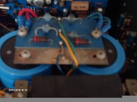
The 250M is repaired and back in operation.
The damage was limited to the 39 ohm resistor and output transistors on the right channel.
The left channel output transistors were replaced as well. Both sides using the MJ21193G & 94G.
The amp was 'worked on' by someone who slapped on whatever combination of output transistors on hand or what they felt was ok to use. They were very free with their use of heat sink compond. I got it all over myself and my cloths. Arron, I'll send you the cleaning bill.
Pete, the filter caps were replaced with 'TECH-CAp 20,000 uF 60V parts. A very nice fit!
The driver transistors were not damaged, so no replacement needed.
Attachments
Last edited:
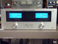
I am the owner of the 250M and want to thank JBLMAR for a repair job well done. About a month after the repair I was playing the amp sourced from my CD player and came back to notice no sound. I was not in the room when the system failed so I am not sure if there was smoke, a blown fuse etc. I am now looking to re-repair this unit and want to see what options I might have? Jblmar do you have any more ideas? Hope to get those blue meters dancing soon again.
Pete,
I'm still much a newbie with the audio electronic repairs. I understand the physics but that's about it although I'm beginning my interests. I'm not sure how the amp failed I just know that when I power the amp on there is no click like usually heard when powering up. Hope this helps
I'm still much a newbie with the audio electronic repairs. I understand the physics but that's about it although I'm beginning my interests. I'm not sure how the amp failed I just know that when I power the amp on there is no click like usually heard when powering up. Hope this helps
"I believe that it is a highly flawed design and this is why I've not rebuilt mine."
You must be right, it only ran for 30 years or so!
"I'm not sure how the amp failed I just know that when I power the amp on there is no click like usually heard when powering up."
It either blew up and is putting out DC, or the cap in the delay circuit has dried up.
You must be right, it only ran for 30 years or so!
"I'm not sure how the amp failed I just know that when I power the amp on there is no click like usually heard when powering up."
It either blew up and is putting out DC, or the cap in the delay circuit has dried up.
"I believe that it is a highly flawed design and this is why I've not rebuilt mine."
You must be right, it only ran for 30 years or so!
The unit that I have blew up when the output was shorted yet the amp has output protection, seems it doesn't work very well. You are welcome to your own opinion, I could go into detail about the design issues but I expect that you will never admit that there is anything wrong with it.
Pete,
I'm still much a newbie with the audio electronic repairs. I understand the physics but that's about it although I'm beginning my interests. I'm not sure how the amp failed I just know that when I power the amp on there is no click like usually heard when powering up. Hope this helps
Let's hope that if there was no shorted output or heat issue that it is just a dried up electrolytic cap. All the small electrolytic caps should be replaced - has this been done in the last 10 years or so?
I've been running one of these for many years. I got it for next to nothing because nearly every device in it was blown. IMO it runs with very little safety margin; too high a line voltage combined with a heavy load might spell disaster. It also doesn't have enough heatsinking for long term high output operation unless you point a fan at it. Whatever you do, don't forget to plug in the bias connector that goes to the sense transistor on the heatsink. Instant blown outputs. Sounds stupid, but easy to do if you have to pull it apart several times. Also, be sure the bias and limit pots are 100% good. Use some Caig or replace them if in doubt. When everything is working correctly it's an OK amp, but easily bested by modern designs. Does look pretty though.
CH
CH
Conrad - I was wondering if you could clarify "plug in the bias connector". I am in the process of attempting to repair one of these amps, but cannot find a single connector on the inside. Perhaps it was a later modification?
This 250 I have appears to have blown finals on both side, positive rail. The NPN's measure fine, but I'll replace them all w/ MJ21193, 94 based on info herein. The relay is missing too, and that may be the hardest part to replace. But this thing otherwise appears to be completely stock. It's been on the 'project' shelf for over 10 years.
Reading this thread I think I will opt to deviate from a stock rebuild and perhaps strongly consider a modernization of the protection circuit at least. Perhaps I will attempt to integrate in a uPC1237 and scrap that protection board altogether. Maybe then some banana output jacks would be in order as well.
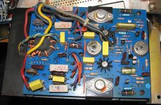
The curious thing is that I can find only ONE 39 Ohm resistor on the board (negative side, under the coax, upper left). It measures 43. -Vcc to Q803 base reads ~42 with drivers removed; s/b 39 too (according to schematic), I just can't find the silly resistor.
This 250 I have appears to have blown finals on both side, positive rail. The NPN's measure fine, but I'll replace them all w/ MJ21193, 94 based on info herein. The relay is missing too, and that may be the hardest part to replace. But this thing otherwise appears to be completely stock. It's been on the 'project' shelf for over 10 years.
Reading this thread I think I will opt to deviate from a stock rebuild and perhaps strongly consider a modernization of the protection circuit at least. Perhaps I will attempt to integrate in a uPC1237 and scrap that protection board altogether. Maybe then some banana output jacks would be in order as well.
The curious thing is that I can find only ONE 39 Ohm resistor on the board (negative side, under the coax, upper left). It measures 43. -Vcc to Q803 base reads ~42 with drivers removed; s/b 39 too (according to schematic), I just can't find the silly resistor.
Attachments
- Home
- Amplifiers
- Solid State
- Marantz 250M Repair