Mr Evil said:If I can make the simulator match reality better then I can avoid this sort of problem in the future.
Hi,
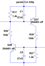
Try using the OFF keyword as in the schematic below. This is handy for analysis of bistable circuits. This schematic was lifted from the protection circuit of syn08's YAP output stage.
Attachments
But the current sources themselves are not the problem, they work fine in isolation. The position clearly does matter though. In this case, it is because in order for one current source to turn on, the other must turn on first. This happens readily in the simulator, in fact I can't prevent it from happening no matter what I do. In reality though, it requires those two extra resistors.Lumba Ogir said:Mr Evil,
the ideal current source properties are the same in any position. Why do you think your very common circuit would particularly represent an exception?
I was optimistic that that was going to be it, but it doesn't make any difference unfortunately. I also tried setting the initial current and voltage explicitly to 0, using different transistor models, and ramping the supply voltages up starting from a slightly negative value, but the circuit always starts.andy_c said:Hi,
Try using the OFF keyword as in the schematic below. This is handy for analysis of bistable circuits. This schematic was lifted from the protection circuit of syn08's YAP output stage.
There's a positive feedback bias mechanism in the whole input stage, an increase in Q7 collector current increases Q9 current and vice versa.
Global negative feedback keeps those currents equal.
This effect is relatively low because of low values of R7 and R10, so a bit of negative feedback by Early effect can hopefully equlize it at some point of equiibrium, but that's still a thin ice.
Your circuit resambles the circuit Andy's attached, and that is basically a thyristor.
In simulation try initial capacitors' charge at zero instead of letting it finding bias point.
PS. To be sure it initializes, try a 100pF+2k series connection to ground from Q7/Q9 bases, should also improve PSRR without sacrificing stability.
andy_c said:
Hi,
Try using the OFF keyword as in the schematic below. This is handy for analysis of bistable circuits. This schematic was lifted from the protection circuit of syn08's YAP output stage.
Another interesting bistable circuit is the PGP power on button here: http://www.synaesthesia.ca/PowerOn-Sch.html
Look at the Q1 Q2 Q3 configuration and the hysteresis that allows flipping between two stable positions. C2 and C3 are for providing a consistent startup state. The momentary action switch is between Sw1 1-4.
I tried everything else mentioned for the simulation, and a few other things like like changing the leakage resistance 'rshunt' to a higher or lower value, but it still starts up. Other bistable circuits I tried, like the one in post #21 do simulate as initially off.
It is essential to explore every idea - to do otherwise is to stagnate.Lumba Ogir said:...but the very best solution is to forget about this kind of combined trickery.
- Status
- This old topic is closed. If you want to reopen this topic, contact a moderator using the "Report Post" button.
- Home
- Amplifiers
- Solid State
- Current source conundrum