Looks Ok to me, why gold? (except of another gold thing on the photo implying you're married)
Any special adhesive to solder properties?
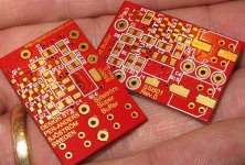
I see you like to have components dense on both sides")
If I were you I'd add another via on the other edge of the PCB to connect all the ground planes.
Any special adhesive to solder properties?
I see you like to have components dense on both sides
If I were you I'd add another via on the other edge of the PCB to connect all the ground planes.
Hi P-A,
Those are very nice looking boards. Care is required with gold and soldering though. Check out this PDF file relating to gold embrittlement of solder joints.
Those are very nice looking boards. Care is required with gold and soldering though. Check out this PDF file relating to gold embrittlement of solder joints.
Hi Hugh,
I'm not a mechanical guy, so I'm certainly no expert on this. But I used to work in the aerospace industry, and I remember the problem from there. Back when they were using discrete, leaded components, all components with gold-plated leads had their leads dipped in a solder pot before being installed on the boards. I'm not sure why this helped, but that's what they did.
I'm not a mechanical guy, so I'm certainly no expert on this. But I used to work in the aerospace industry, and I remember the problem from there. Back when they were using discrete, leaded components, all components with gold-plated leads had their leads dipped in a solder pot before being installed on the boards. I'm not sure why this helped, but that's what they did.
Andy,
I'd guess it's a phase change issue, which is related to how quickly the solder cools. Dipped into a solder pot, the temperatures are more uniform through the lead, and will thus cool slower on withdrawal, and this could reduce the embrittlement at subsequent installation because the operation would then be much quicker since it's already tinned.
Those microphotos were alarming, with shear lines like a broken ice sheet. No wonder the SMDs literally fell off the board.
Hugh
peranders said:What do you think of my latest work?, 4-layer, gold pads
Looks good. Used a similar circuit for impedance transformations in long wave receivers to couple Hi-Z tuned loops to Lo-Z antenna connections. If you do the work right, pay attention to layout and component quality, it'll work from DC to ~100MHz. Quite a bit more than needed, but it's almost impossible to get overdrive that'll cause cross modulations.
So, is that what you're doing here?
Re: Re: Diamond Buffer - Super Buffer

Thanks everyone for the positive words.
Audio and audio requires more. Why? More is better and also it even sounds betterMiles Prower said:
Looks good. Used a similar circuit for impedance transformations in long wave receivers to couple Hi-Z tuned loops to Lo-Z antenna connections. If you do the work right, pay attention to layout and component quality, it'll work from DC to ~100MHz. Quite a bit more than needed, but it's almost impossible to get overdrive that'll cause cross modulations.
So, is that what you're doing here?
Thanks everyone for the positive words.
Just press the keys on the keyboard.... only if you use true type fonts that is.darkfenriz said:BTW how did you force protel to understand scandinavian letters?
The gold is not electroplated. It's immersion gold.AKSA said:Thanks Andy,
This is sufficient evidence for me to move away from Au electroplated boards. It is clear that gold embrittlement causes reliability problems, even at very thin plating levels.
Hugh
Thanks for the info. I have read a little about immersion gold also and what that is.andy_c said:Hi P-A,
Those are very nice looking boards. Care is required with gold and soldering though. Check out this PDF file relating to gold embrittlement of solder joints.
Immersion gold is so thin (only a few atoms) so it will dissolve when the pad is soldered.
I have been told the same, and also use immersion gold plated PCBs for some time now.......
Haven't experienced any problems, and they are so much easier to solder on
- Status
- This old topic is closed. If you want to reopen this topic, contact a moderator using the "Report Post" button.
- Home
- Amplifiers
- Solid State
- Diamond Buffer - Super Buffer