Krill amplifier
Hi c2cthomas
Thanks for your answer.
In fact I was looking for the layout of the board, I looked all the posts
and the only one I saw doesn't correspond to the latest schematic, even
thought the outhor says so.
Truthly I got a bit discouraged for not seing the right layout, it seemed
to me that it was never published. May be yes, may be not, I never found it.
Thanks for your kind information anyway.
Hi jmateus --
No, the board layout has not been published here. Steve Dunlap mentioned in the other Krill thread that the computer files are in storage and he doesn't have access to them.
Steve has been selling the boards if you are interested. They can be used for either the 50W or 100W version. The correct schematic for the 50W version is in post #1460 of the Krill thread. There is also a BOM in either the post before or after #1460. The changes for the 100W amp are pretty trivial.
Hope this helps and that you decide to build the Krill amplifier.
Phil
Re: Krill amplifier
Is this what you are looking for?
jmateus said:Hi c2cthomas
Thanks for your answer.
In fact I was looking for the layout of the board, I looked all the posts
and the only one I saw doesn't correspond to the latest schematic, even
thought the outhor says so.
Truthly I got a bit discouraged for not seing the right layout, it seemed
to me that it was never published. May be yes, may be not, I never found it.
Thanks for your kind information anyway.
Is this what you are looking for?
Attachments
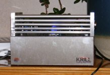
Finally my krill works ")
This is a stereo 50watt version using power darlingtons. (MJ11015 /016) along with tip41/42 and MPSA56/MPSA06 transistors following steve's original circuit diagram
Impressions
(using Lecson AC1 pre-amp and CD player with Leak 16 ohm speakers (1964 vintage))
No switch on thump ( nice ) no hiss or humm. Good clear imaging, at least the equivlent of the Lecson AP1 poweramp with better bass control. As my first real topend construction project i'm very happy.
Many thanks steve for sharing your design.
Alan
PS for the mods and other safety conscious folks, I will add transistors covers when fully finished - there is 70+volts exposed currently
This is a stereo 50watt version using power darlingtons. (MJ11015 /016) along with tip41/42 and MPSA56/MPSA06 transistors following steve's original circuit diagram
Impressions
(using Lecson AC1 pre-amp and CD player with Leak 16 ohm speakers (1964 vintage))
No switch on thump ( nice
) no hiss or humm. Good clear imaging, at least the equivlent of the Lecson AP1 poweramp with better bass control. As my first real topend construction project i'm very happy.Many thanks steve for sharing your design.
Alan
PS for the mods and other safety conscious folks, I will add transistors covers when fully finished - there is 70+volts exposed currently
Attachments
PH104 said:Alan -- Congratulations!! I hope to follow you soon with my listening impressions.
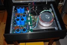
What is that top assembly where the transistors are bolted?
Phil
I'll drag the camera out tomorrow
the base is a wooden box with the PSU (transformer / boards) and connectors on the back.the top is two 1/2" by 6" by 3" slabs of aluminium with 19 off 8mm ali tubes, compression fitted into holes drilled in the slabs, overall @ 10" wide. this covers the amp boards and lifts up for access / adjustment. Drilled for the T03 Darlingtons and the diode temp compensation.
Its OK as a heatsink for music power, on music no appreciable temp change after one hour at moderate (SHMBO turn it down!) levels - gets quite hot (50+C) when run during testing at full sine wave power (55watts/channel) into a 6 ohm dummy load . I doubt it would be any good on a 100 watt amp (2 by 100) instead of 2 by 50. Lot of labour but fairly cheap
Edit - never could spell aluminium

jkeny said:Spiny,
congrats on the build - interesting looking casing - can you tell more/more pics?
What about mid/highs - any impressions?
Much the same as my normal Lecson AC1/AP1 combination. Its my only benchmark - I'm not dragging the matching leak Stereo 20 out of the garage to compare
Its solid though with good imaging and no tizz on peaks, vocals are clear and not muddied and well placed. I would say its a match for the AP1 and there are not many amps I'd say that for these days
Note both the AC1 and AP1 have been re-capped recently by me - a great improvement on the original, they are 30 years old after all
jkeny said:I don't know the Lecson amps so I was not sure of their quality - looked them up but couldn't find a review.
Pretty good result for the Krill then!!
I found a couple of very old reviews at this web site: http://www.lothar-kissinger.de/lecson-audio/htm/newspaper.htm
The Lecson looks to be some very nice "vintage" gear - sort of like me!
According to this article : http://www.tnt-audio.com/ampli/meridian551_e.html the designer of the Lecson amplifier was Robert (Bob) Stuart - co-founder of Boothroyd-Stuart who make Meridian amps.
Krill amplifier
Hi Steve
Thanks for your effort.
Yes and no, the component layout is useful only if I had the copper design.
I didn't know you'd sell the boards, I was looking for the copper layout but
the component silk screen is helpful.
BTW if I want to buy the boards how much are they?
Thanks
Hi Steve
Thanks for your effort.
Yes and no, the component layout is useful only if I had the copper design.
I didn't know you'd sell the boards, I was looking for the copper layout but
the component silk screen is helpful.
BTW if I want to buy the boards how much are they?
Thanks
originally posted by spiny{/I]
......gets quite hot (50+C) when run during testing at full sine wave power (55watts/channel) into a 6 ohm dummy load.
Spiny - How long did you run the amp full power before measuring temperature?
Thanks.
Hi,
I do maximum power and part power testing using a switch (-20dB & 0dB) for the test signal. I have the 0dB signal on for the minimum length of time, usually one or two seconds.
Allow sufficient time between tests to ensure neither the load nor the amplifier get too warm.
I am testing the electronics not the heatsink.
Re: Krill amplifier
Hi jmateus,
The PDFs of the copper are to large to post here. If you E-mail me, I will send them to you along with board prices.
jmateus said:Hi Steve
Thanks for your effort.
Yes and no, the component layout is useful only if I had the copper design.
I didn't know you'd sell the boards, I was looking for the copper layout but
the component silk screen is helpful.
BTW if I want to buy the boards how much are they?
Thanks
Hi jmateus,
The PDFs of the copper are to large to post here. If you E-mail me, I will send them to you along with board prices.
Steve Dunlap said:Hi Spiny,
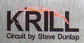
Nice work. I'm glad you like the design. I like the Krill logo you put on the front.
thanks for the comments. Here's a better shot of the logo
Attachments
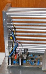
jkeny said:Spiny,
congrats on the build - interesting looking casing - can you tell more/more pics?
What about mid/highs - any impressions?
Here is a shot with the top open and one side showing. The ali bars are more obvious now
Attachments
PH104 said:
Spiny - How long did you run the amp full power before measuring temperature?
Thanks.
I've stuck a thermometer on it and run it at 40 watts a side (80 watts into 6.6 ohms)
after 15 mins the temp reaches 60 C at 30 mins 70C and stabilizes this appears to be the point the losses equal the heat input. temp measured on the 1/2" slab. At this point my dummy loads are running at 120 degrees!
(pair of 3.3ohm 50watt wirewound per channel. I need to put a fan on them 
- Home
- Amplifiers
- Solid State
- Krill construction thread - 100W version