Cambridge a1
Could you possibly send me copy?Hi Billicar,
i have the schematic, send me a email and i will send it to you. Maxpou
Could you possibly send me copy? My e-mail: og@kw.uaHi Billicar,
i have the schematic, send me a email and i will send it to you. Maxpou
I'd really find this schematic for mk1 useful. Please could you email it to me a dave@gdbe.co.uk
Many Many Thanks
Dave B
Many Many Thanks
Dave B
The A1 went through a few revisions, not always with a new "Mk" number. The first was discrete but then they went to TDA1514 chip amps, and the one I have was based on a LM4765 chip. When I got it there was an exploded capacitor, the chip had fried and burnt a hole through the board.
I'd be interested in the schematic for the initial version that's a discrete amp.
I'd be interested in the schematic for the initial version that's a discrete amp.
I'd be interested in the schematic for the initial version that's a discrete amp.
Me also - I have a second-hand one where the RH channel just outputs a hum and there's a (literally) blown BC639 transistor on the power amp pcb. I'm replacing it when my ebay order arrives in the next couple of days, but this is really just a "hit and hope" approach.
The schematic might give me a clue as to why it exploded in the first place!

Cambridge Audio A1 v3.0 schematic
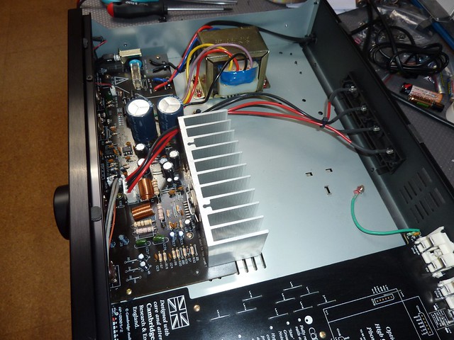
I bought a few months ago a Cambridge Audio A1 v3.0, the one with a single LM4766.
I've been modifying it... not always for better, because in the process some supposed improvements had to be undone.
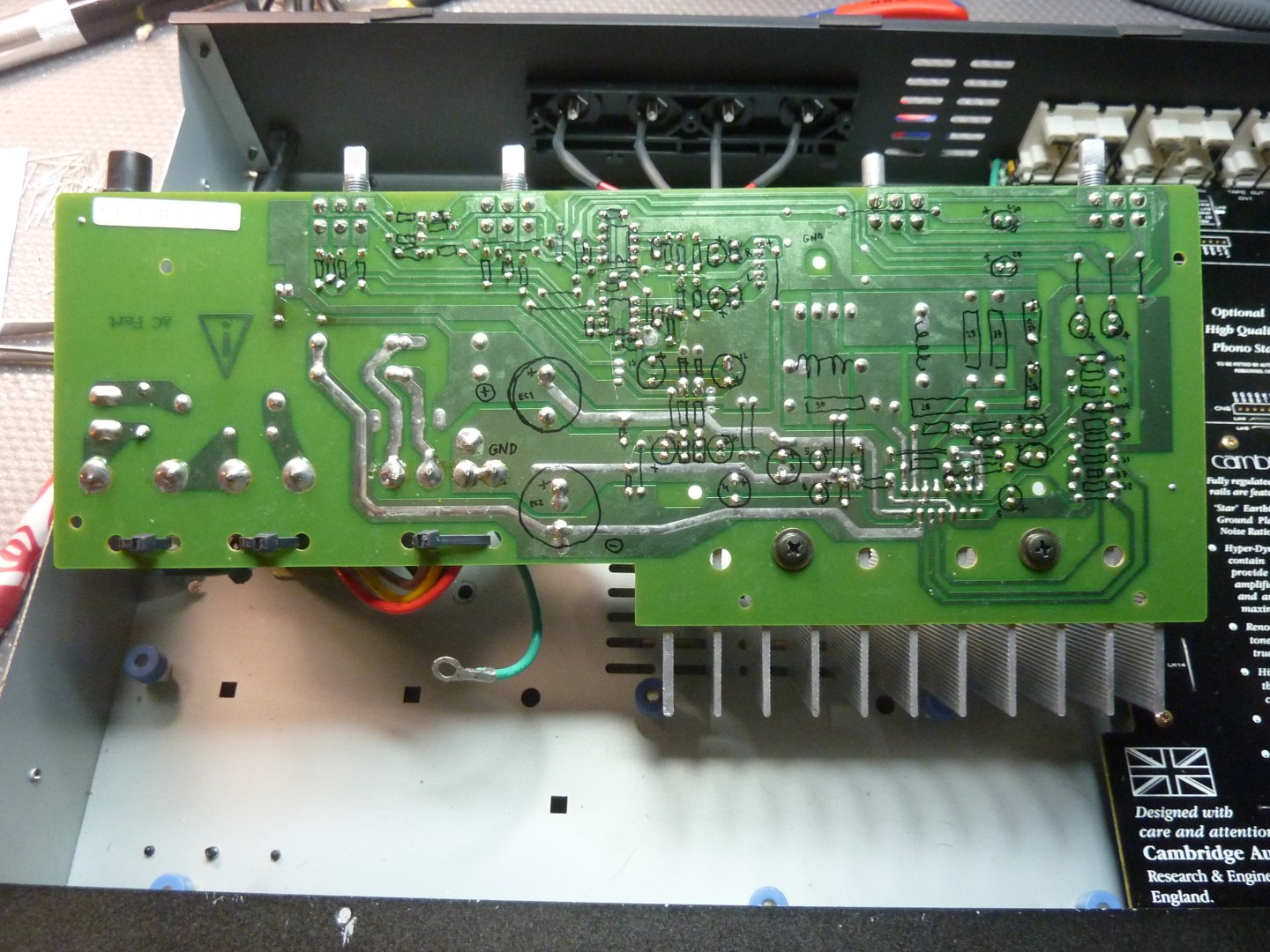
When I started this, search the web for the schematic and always ended up in web pages were everybody else was looking for the same as me, and at most, found the schematic for other versions of the CA A1. So I've been drawing the schematic myself and I want to share it with you guys, in retribution for a lot I've learned by reading some posts in this forum.
The schematic is not error free, and is for now a 1st version of only the pre+amp PCB. I haven't removed the input board yet (the one with the RCAs and input selector), and I don't have the phono board.
You can find pictures of my CA A1 in my Flickr album
If anyone find errors, please be so kind to point them for me, so I can correct them. Anyone can share this in any way, but I assume no responsibility whatsoever for what you do with my shared knowledge, mistakes or ignorance
Cumps
I bought a few months ago a Cambridge Audio A1 v3.0, the one with a single LM4766.
I've been modifying it... not always for better, because in the process some supposed improvements had to be undone.
When I started this, search the web for the schematic and always ended up in web pages were everybody else was looking for the same as me, and at most, found the schematic for other versions of the CA A1. So I've been drawing the schematic myself and I want to share it with you guys, in retribution for a lot I've learned by reading some posts in this forum.
The schematic is not error free, and is for now a 1st version of only the pre+amp PCB. I haven't removed the input board yet (the one with the RCAs and input selector), and I don't have the phono board.
An externally hosted image should be here but it was not working when we last tested it.
You can find pictures of my CA A1 in my Flickr album
If anyone find errors, please be so kind to point them for me, so I can correct them. Anyone can share this in any way, but I assume no responsibility whatsoever for what you do with my shared knowledge, mistakes or ignorance
Cumps
Attachments
Some guys will be very thankful for you efforts there, Montymore. Nice Going.
To cover some more variations and keep them together in a thread, here is a link to Cambridge's own schematic + BOM
for related models A1 - A1v2 - A1mk3 se - A2. Cambridge Audio A1 | Owners/Service Manuals, Schematics, Free Download, Reviews | HiFi Engine
It seems the maketing dept. kept running out of impressive ways to relabel the same basic Chipamp product.
The Mk3 Schematics are available here - Cambridge Audio A1 | Owners/Service Manuals, Schematics, Free Download, Reviews | HiFi Engine
Sorry Ian, you beat me to it.
Sorry Ian, you beat me to it.
The Mk3 Schematics are available here - Cambridge Audio A1 | Owners/Service Manuals, Schematics, Free Download, Reviews | HiFi Engine
Sorry Ian, you beat me to it.
Sorry KatieandDad, but it's not.
The schematics there is for the versions "A1 - A1v2 - A1mk3 se - A2", as stated by Ian Finch, that have the two TDA1514, and not for the A1 v3.0 with a single LM4766.
Attached goes now my BOM, so far.
Attachments
Some corrections done to the schematic so it goes to rev 0.2
I intend to redo the schematic with a component layout more friendly to understand the circuitry.
The present layout is as is because it was drawn mostly following the components location on the real PCB.
An externally hosted image should be here but it was not working when we last tested it.
I intend to redo the schematic with a component layout more friendly to understand the circuitry.
The present layout is as is because it was drawn mostly following the components location on the real PCB.
Attachments
- Home
- Amplifiers
- Solid State
- Cambridge Audio A1 Schematic