I was wondering if there is any collective knowledge on the board as to some good modifications to the first generation Adcom GFA-535 or GFA-555? I've got the schematics for the 555 (the 535 appears to be very similar but scaled down). The designs look to be quite solid, but sound a bit harsh in the upper octaves.
They strike me a good candidates for modification as there are a ton of them out there and you can pick them up quite cheaply. In the case of the 555, there more room in that amp chassis than in my Miata trunk...
So is there anything good out there for these fairly good performers?
Sheldon
They strike me a good candidates for modification as there are a ton of them out there and you can pick them up quite cheaply. In the case of the 555, there more room in that amp chassis than in my Miata trunk...
So is there anything good out there for these fairly good performers?
Sheldon
Try this thread for tips.....
http://www.diyaudio.com/forums/showthread.php?threadid=5280&highlight=adcom
http://www.diyaudio.com/forums/showthread.php?threadid=5280&highlight=adcom
Thanks for the pointer to that adcom thread. I've been through that several times. I downloaded the schematic and the power supply regulator circuit as well.
that thread doesn't really address mods to these amps and whether it's effective, worth it, etc...
That caught my eye was: "Personally, I would score a few of these and run them till they die and then update them. If you wait long enough, an update will be issued." -- Nelson Pass
Sheldon
that thread doesn't really address mods to these amps and whether it's effective, worth it, etc...
That caught my eye was: "Personally, I would score a few of these and run them till they die and then update them. If you wait long enough, an update will be issued." -- Nelson Pass
Sheldon
535 mod
Sheldon,
Quite a few years back I tweaked an Adcom 535 for my brother-in-law and found it to be a rather nice amp.
I don't have the amp here, so this is just from memory. The biggest improvement came from playing with the front end. It uses a bipolar differential pair at the input. Unlike the 555 schematic, the pair is simply loaded with a resistor, not a current source. I added bootstrap cascode transistors to the two bipolar input transistors and increased the operating point of the transistors to slightly higher current. This seemed to nicely open up the high end and soundstage with no downside. Of course, you need to change the associated resistors to compensate for the different currents.
I think I also applied standard tweaks like adding a bit more power supply capacitance locally distributed close to the output transistors and that helped out the low end a bit.
---Gary
Bootstrap Cascode
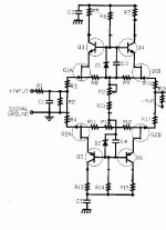
Here's an input circuit from E. Borbely showing the type of bootstrap cascode that I used in the Adcom. Of course, the Adcom uses bipolar inputs, not jfets and the circuit would only need the top half. Still, for those not familiar with bootstrap cascoding, it illustrates the principle.
---Gary
Here's an input circuit from E. Borbely showing the type of bootstrap cascode that I used in the Adcom. Of course, the Adcom uses bipolar inputs, not jfets and the circuit would only need the top half. Still, for those not familiar with bootstrap cascoding, it illustrates the principle.
---Gary
Attachments
Adcom mods
Hello Sheldon,
I own an Adcom GFA535 and, while it is a nice enough amp, I couldn't get my 6mm2 speakercable in the terminals so I replaced those. And while I was at it, I also removed the complete "speaker A-B" circuitry. Can't tell if it sounds very much different though, electronics upgrade seems more worthwhile sonically.
Greetings,
Jarno.
BTW. I like your website, I'm into photography as well.
If you run into an extra 555, let me know, I'd love to have another one or two.
Before the major butchery that is my current version of the (original) 555, I got rid of the electrolytics in the feedback and input paths and put in a servo. The servo was a non-inverting integrator, set to about a 3 or 4 Hz corner frequency, with an extra passive RC pole (fc of about 50 Hz) at the output. The extra pole was put in just in case there were any extraneous noises coming out of the servo.
It worked quite well for 15 years, the only downside being some turn-off thumps. I'm sure that playing with the charge/discharge rate of the servo's power supply would have dethumped the circuit, but I was always too lazy to fix it.

The first thing I did to my 555 was to replace the input jacks. The dreaded previous owner, totally screwed them up. Other than that, it's bone stock.
The 535 had it's output jacks replaced before I ever powered it up (I used superior electric gold plated 5 way posts on an FR4 circuit board). I also replaced the input jacks, and bypassed the bias electrolytic cap with a film, and replaced the bias pots with 10 turn ones. All the power supply caps are already bypassed and the feedback electrolytic cap is also bypassed.
I played with the bias on the outputs to try to find the minimum distortion point, but it seems that the bias drifts with time too much if I crank up the bias (not enough temperature feedback to keep the higher bias stable).
Gary-
Were you able to implement the cascode circuit on the original PCB?!
Sheldon
Well I did put all of this on the original circuit board but I used a lot of free space wiring. Its not as bad as you might think, although it definitely looks as if someone modified it.stokessd said:Were you able to implement the cascode circuit on the original PCB?!
Basically, I just unsoldered the original bipolar collector leads and soldered these to the emitters of the new cascode transistors. Collectors of the cascode transistor goes back in the circuit board lead. The two base leads and wired together in free space, the bootstrap zener goes from this lead to the diff pair emitter resistor/current source (don't recall which). Add another resistor from the cascode transistor base up to the postive power supply and you're done. Just don't forget to account for the extra current flowing into the diff pair resistor/current source. I think I used LM336Z2.5, which are low noise 2.5v zeners biased at about 1ma.
---Gary
The No Brainer 535 II 'Tweak'
Hello,
I'm a 535 II owner who's relatively new to audio and DIY. I'm building an entry- level system based on Arthur Salvatore's guidance at http://www.high-endaudio.com/rec.html (highly recommended). Anyhow, here's something I picked up somewhere on the net (audioreview?): replace the fuses with ceramic fuses for about $10 or less (Radioshack).
I tried it and was shocked with the result; it has to be the best per dollar improvement possible. I've e-mailed Nelson Pass on the subject, and his response was:
"I don't know offhand, but there is resistance and signal modulation in the fuses, and the bigger the value of the fuse, the less of that you'll see. Another possibility is that one or more of the fuse connectors was oxidized or dirty, which really degrades the connection, in which case new fuses might have cured that.
"Probably 1 of the fuses is the AC line fuse, which I would not fool with further, but the remaining are in series with the supply rails of each channel. You might consider bypassing those with wire"
My grateful thanks to Mr. Pass for his response. I've replaced the AC line fuse with an equivilent 5 amp ceramic, and the four others (4 amp) went to 15 Amps. How can you go wrong for a $10 tweak?
The fuse trick
I totally agree with stephen on the fuse issue.
We´ve got a coupple of 535´s for "portable" use one as part of a party or mini pa in an aluminium case with a CD a mixer microphone etc. This is used together with a pair of mini monitors with PHL 8" bass/mid and Wisaton ribbon tweeters. This sounds good and You can play ridicously loud for such a small setup. But the Adcom kept blowing fuses and as it was screwed down int the alucase i got tired of constant dissasembly and replaced rail fuse with wires and fuse sockets in the case. This happened to be Accuphase sockets for 10x36mm fuses (same as in Fluke´s)
put in a pair of slow 15A ceramic fuses and the amp sounds twice as powerfull! Has´nt blown a fuse, or nothing else, for two Years.
The power supply regulator is a great mod!! It makes the amp sound much beter. With a regulated voltage you dont need to change the input circuit because the current accross the stage will be constant as the voltage accross the resistors is now constant.
It tightens up the sound a lot. The highs are better and the bass more defined.
It tightens up the sound a lot. The highs are better and the bass more defined.
stokessd said:The first thing I did to my 555 was to replace the input jacks. The dreaded previous owner, totally screwed them up. Other than that, it's bone stock.
Sheldon
I got a 555 recently in the same siuation. Where did you find the replacement parts for the input jacks? Do you have any instruction to replace that? Thanks!
Roscoe Primrose said:Another option for the 535 is to add anothe pair of output transistors to each channel, as there are more holes in the PCB than they actually put in the amp. This will require drilling the heatsink and adding emitter resistors for the added transistors...
Peace
Those extra holes are for the GFA-545 which used the exact same boards. The 555 was a different Design. The 545II is one of my favorite Adcoms.
This is an ancient thread, but fits in with what I would like to do. I've got the 535 (not 535-II). I bought this many years ago, so it is somwhere between 15 and 20 years old. It has done an admirable job on a budget.
One easy upgrade is to replace the 4 big caps (6800 uF each). I know that cap quality is much better than it was 20 years ago and the United Chemicons are a great deal.
My question is, if I want to up the capacitance, how much is too much capacitance? Could I go up to 10k uF without overloading the trafos? Would I get any real gain by doing so?
I'll probably also purchase some Dale RN resistors and remove the awful speaker connectors. I'm tired of pulling the speaker wire every two years, trimming, and stripping to have clean copper.
That's exactly what I did (removing speaker switches), remove the wiring harness to the connectors on the frontpanel altogether. It's an awful big mess of wiring running through the already cramped amp enclosure.
Regarding the caps, if they are 6.8mF now, going to 10mF is not going to destroy anything. Going way higher, say 47mF a piece or so, you might want to add something to limit the startup current.
IMHO, more gain is to be had from using better capacitance, by using the suggestion in Walt Jungs "Picking Capacitors" article, and bypassing the big elco's with filmcaps.
My main gripe with these amps (I got two, one for stereo low, one for mid-high, with a active crossover), is the noisy transformer. I really would like to replace them, but they are quite an exotic type.
Best regards,
Jarno.
Guys, thanks for the input. Jarno, ok..that's what I thought re. capacitance. An increase to 10k uF is fine.
Yeah, those trafos are pretty big and heavy. I've wondered about buying a toroid kit and custom winding a toroid for this unit. It would be a heck of a hassle according to some, but might be worth it since the kits run around $40 to $60 and I could wind to the correct voltage.
Yeah, those trafos are pretty big and heavy. I've wondered about buying a toroid kit and custom winding a toroid for this unit. It would be a heck of a hassle according to some, but might be worth it since the kits run around $40 to $60 and I could wind to the correct voltage.
- Status
- This old topic is closed. If you want to reopen this topic, contact a moderator using the "Report Post" button.
- Home
- Amplifiers
- Solid State
- Modifications to the Adcom 535 or 555?