In the power amp section, I would like to use a 30-0-30 3 amp transformer. Is this possible or is it limited to the 25-0-25 5 amp noted?
Also, would one recommend heatsinks on the bd139/140's?
Thanks
http://sound.westhost.com/project27b.htm
Also, would one recommend heatsinks on the bd139/140's?
Thanks
http://sound.westhost.com/project27b.htm
The short answer is no, the voltage is too high and the current too low.
The simplest thing is to follow Rod Elliott's recommendations. You will have enough problems just getting that right without adding to them.
The cost and effort of building an amplifier mean that there's little point in cutting corners.
w
The simplest thing is to follow Rod Elliott's recommendations. You will have enough problems just getting that right without adding to them.
The cost and effort of building an amplifier mean that there's little point in cutting corners.
w
30-0-30 VAC transformer with generate somthing like
30 x 1.4 or even maybe 30 x 1.5 = 42-45 Volt
2 x 42-45V = 84-90 Volt
For BD139/140 this is the critical voltage, MAX 80 Volt. They may survive, they may not.
Different exemplars of any transistor can take a bit more than absolute max rating.
Others will be destroyed.
Trafo 25-0-25 will generate 2x35-2x38 Volt, and this is within safety margins for BD139/140.
I would advice to not experiment, but use the recommended 2x24 or 2x25 VAC trafos.
There will be a couple of Watts in BD139/140, maybe 1-3 Watt, when Higher output levels.
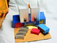
I should cut from some 1mm thick aliuminium pieces.
Size ~ 20-25x40-50 mm (like 1" x 2") and screw them onto those BD139/140.
I usually bend the wings of those plates to make the whole thing not to wide to fit.
This will be enough to keep them TO-126 from getting too hot.
Not at all as big as in attachment. Those are for bigger TO-220 Output transistors.
But I made them out of 1 mm Alumiumsheet.
30 x 1.4 or even maybe 30 x 1.5 = 42-45 Volt
2 x 42-45V = 84-90 Volt
For BD139/140 this is the critical voltage, MAX 80 Volt. They may survive, they may not.
Different exemplars of any transistor can take a bit more than absolute max rating.
Others will be destroyed.
Trafo 25-0-25 will generate 2x35-2x38 Volt, and this is within safety margins for BD139/140.
I would advice to not experiment, but use the recommended 2x24 or 2x25 VAC trafos.
There will be a couple of Watts in BD139/140, maybe 1-3 Watt, when Higher output levels.
I should cut from some 1mm thick aliuminium pieces.
Size ~ 20-25x40-50 mm (like 1" x 2") and screw them onto those BD139/140.
I usually bend the wings of those plates to make the whole thing not to wide to fit.
This will be enough to keep them TO-126 from getting too hot.
Not at all as big as in attachment. Those are for bigger TO-220 Output transistors.
But I made them out of 1 mm Alumiumsheet.
Attachments
By Rtill - In the power amp section, I would like to use a 30-0-30 3 amp transformer. Is this possible or is it limited to the 25-0-25 5 amp noted?
What a simple, stable amp. For the same price , just use better
trannies (see attached schema) this one is the 27B with
45-0-45v operation and could run nicely with over 50v.
Dont expect it to be a Hi-fi amp , but it will do a guitar real
good. Inputs (Q1/2) run at 1 and 3mA, Q3 runs at 10mA (small
radioshack to-220 heatsink), Q4/5 also run at 10mA (I would
also put these on separate small to-220 heatsinks, contrary
to rod's recommendation).
To really make a durable amp the mj15003/4 would be
the best for outputs.
OS
Attachments
ostripper said:this one is the 27B with 45-0-45v operation and could run nicely with over 50v.
You still can't use the 3A transformer.
w
Hi,
change the VAS from 340 to a low Cob transistor.
Add an emitter resistor to the VAS. In ESP schematic Re~30r
In Os schematic use ~56r for Re.
Change input DC blocking cap (C1) to 470nF.
Os,
do you really want 1r0 for output emitter resistors?
Would you recommend input emitter resistors? Maybe 100r to 330r?
change the VAS from 340 to a low Cob transistor.
This is not a hi-fi amp, just a crude "wire with gain".
Look at Cdom , it is 220p, that will "swamp" any amount of Cob
regardless of device (even use a mje15032,won't need a HS).
This amp was designed to be a basic instrument amp with
ultra low parts count ,you could mount the diodes on one
of the drivers for more thermal stability (CFP) in
simulation it seems a little underbiased (50mA)but I think that was intended seeing it's purpose.
It also triangulates a sqaure wave at 15khz ,which backs
my opinion of it..not a Hi-fi amp.
A 200R trim in series with the diodes would give a nice touch
to the amp. As far as degenerating the input diff. this amp
does not offer much OLG (50DB) , so I think rod intended for
that as well.
OS
You still can't use the 3A transformer.
yes ,you could, but you would run out of current ,amp
would clip like hell (good for guitar).
for the original design, would this be the correct transformer to use?
167P50
If I am correct, since it is using 5 amp fuses in the power supply section, it would use a 5 amp transformer. It isn't really specified in the project.
http://www.hammondmfg.com/pdf/5c0020-21.pdf
167P50
If I am correct, since it is using 5 amp fuses in the power supply section, it would use a 5 amp transformer. It isn't really specified in the project.
http://www.hammondmfg.com/pdf/5c0020-21.pdf
rtill said:Is it the correct amount of Amps? 5 amps just seems high to me.
5A is probably right for continuous sine wave. Modern practice (for both home and professional equipment) is to size the VA rating of the trafo for current draw with 1/8 power with pink noise signal. Buy this amp and the trafo will be an amp and a half if you're lucky.
I hope this is not you suggesting we lower our standards to match PMPO?wg_ski said:Modern practice (for both home and professional equipment) is to size the VA rating of the trafo for current draw with 1/8 power with pink noise signal.
Of course not. But a 3 amp transformer will work, will make the amp put out full power, and probably be better than what you get in a store-bought unit. If you played a continuous sine wave, it would likely overheat in maybe 15 minutes. Chances are the heatsink would boil spit long before then.
Modern amps, even ones that put out full advertised power, have the trafos undersized. Sizing it for full sine wave is overkill. The real answer lies somewhere in between. Personally, I size mine for 1/3 power at 4 ohms and 1/8 power at 2 - continuously. That's still about 50% more VA than typical, which is 1/8 power at 4 ohms.
Modern amps, even ones that put out full advertised power, have the trafos undersized. Sizing it for full sine wave is overkill. The real answer lies somewhere in between. Personally, I size mine for 1/3 power at 4 ohms and 1/8 power at 2 - continuously. That's still about 50% more VA than typical, which is 1/8 power at 4 ohms.
Yepp!wg_ski said:Sizing it for full sine wave is overkill. The real answer lies somewhere in between.
")
regards
Here's what Rod says 'The transformer rating should be 150VA minimum - there is no maximum, but the larger sizes start to get seriously expensive. Anything over 250VA is overkill, and will provide no benefit.'
Transformer choice is as much about experience of the design in question in it's intended venue as it is about calculation.
The amplifier is intended to work down to 4 ohm load.
Since the current draw woud be greater @ 30vrms the 3A 180VA transformer is getting a bit marginal at 4 ohms, plus it leads into other complications.
It's much easier to build an amplifier exactly as someone has built it before in these circumstances, because if you have problems you have to debug there are less potential sources of error and more chances someone can tell you spot voltages.
As ostripper points out, the distortion characteristics would be more pronounced with the 30v transformer, but this is not necessarily desirable in a solid-state instrument amplifier. Distortion is easy to add, and if you can't get a clean sound then it can be very frustrating. Even if you play dirty now, this may not always be the case.
So your 5A choice might be slightly more rugged than is absolutely necessary but it is a good conservative one which improves the likelihood of your building a versatile, robust and satisfactory working amplifier.
You can save a few bucks and go right down to 3A if you can find one conveniently.
w
- Status
- This old topic is closed. If you want to reopen this topic, contact a moderator using the "Report Post" button.
- Home
- Amplifiers
- Solid State
- elliot sound project 27b question