i thought like posting that ..... feel free to edit it ...
happy regards sakis ( with sexy avatar )
Vintage amplifier repair/restore tips by east electronics part 1
1-All vintage amplifiers need recapping (most electrolytic inside a vintage amplifiers are likely to be gone. Apply not only to rectifier board but also the all device.
2-By the same logic resistors should be taken care off or at least take a look at to see for variations from the original value. (Replacing also from cheap carbon type to a metal film is also an upgrade)
3-Often replacing electrolytic with higher quality caps will make difference in the overall performance.
4-All changes to be made have to have a symmetric effect .IE adding 100mf bypass cap next to positive rail ,next to output transistor should followed by the same on the negative side .
5- Adding bypass caps of 0.1 mfd to rectifier board electrolytic makes them faster.
6- There is almost no limit of how much rail capacitance you may add .There is only waste of them .IE in a Japanese AKAI amp that have a max out of 35+35W and capacitance of 2x4700 mfd exists on the power supply unit …. You may upgrade up to 2x10.000 mfd but farther than that to my opinion is a waste.
7- Replacing outputs have to be done with caution .If outputs are obsolete you can go to the nearest pair that is on production today. Changes also have to be symmetric! You can not leave the existing PNP out put BJT and replace only the NPN. Also may be other channel of existing amplifier is working ok but replacement of all outputs also will guaranty equal performance between the two channels.
8-Outputs have to be matched for optimum performance .Especially if more than two exist on the circuit .Never buy transistors of different brand .Always take care of the brand and the supplier you buy from since a lot of fakes are in the market world wide.
9-All the above apply for any other transistor (BJT/ MOSFET) you will need to replace. All the above concept applies to the entire transistor needed to be replaced no matter what the stage of the amp exist in.
10-LTP transistors (first stage) should be chosen for low noise and high hfe and frequency response.
Ccs transistors (first-second stages) should also be equal to the task
Vas amplifier / driver transistors like the above plus they need to also have enough power to be able to work as a replacement.
11- A schematic of the amplifier is always a good thing to start .To be able to restore/repair one amp you may be able to make replacements and changes but up to a small margin .Schematic is always useful in case you have components burned beyond recognition. Original values like offset and idle of the amplifier should be kept with in factory settings more or less.
12- Anything you change respecting idle offset and/or others will have side effects on the performance of the amplifier. Power should not be your conquest always. Combination of quality, power, and stability will result to performance.
13- Extra care should be taken together with caution were transistors (output/drivers/ vbe multipliers are to be attached on any heat sink. Insulation required most of the times between transistors and heat sinks .Thermo transfer paste ( white ) should be replaced with fresh and you can apply as much as you like …the excessive amount can be cleaned later .
14-Trimmers existing inside the amp adjusting offset and bias might be dirty or broken (often a good reason to take you to immediate death even though most of other components are already replaced) Replacing them to a multi turn trimmer will provide you with more precise adjustments and this can also be very useful if you replaced with other outputs/drivers that might require more or less bias or adjustments.
15- To repair restore any amplifier you will need equipment like signal generator, scope, and dummy load as a basic equipment. Precise repairs, upgrading, and restoration cannot be done with out them.
16- Look very carefully for any cannibalization signs IE somebody in the past repaired this amp and used anything available in his workbench. There a schematic might be handy once again but also you may start to look and recognize if any of the components replaced is fake .This is mostly happening to the output transistors. Please notice that proper number of transistor doesn’t make a replacement .Brand and quality is also very important. You have to think of your amplifier as a horse car ……with 4 horses for example ….All horses have to be the same family the same age and the same build. If you run a horse car with two pony and two stallions ….then the pony will slow down the all horse car …..Even between the same brands of horses same age and same build, horse people in the past used to place male horses upfront and female in the back …. So male could not see or smell the female ….And goes on….
Power up!!!!!! (Not for class A amplifiers )
1- After we make sure that all our new components are placed properly and also all the remaining components are still in good condition and all the things are more than double checked for correct polarity and orientation and so on , there is a few things you can do to have a trouble free start up.
2- Before any power up attempt you should set the offset trimmer ( if existing ) somewhere in the middle and the idle trimmer CCW meaning the highest resistance available to make sure that start up is going to be with as less idle current is possible .
3- Connect in serious with mains one bulb rated 60-150w depending on the power of the power amplifier (generally 60w is a good choice) or 22R/2W instead of fuses in both rails (if fuse holders existing) either of these techniques work as a power limiter in case your amp is faulty or any of transistors or diodes are short circuited. ( you can actually do both to be on the safe side ) Connect also a fused ampere meter to the positive rail .If something is wrong you will see the bulb lighting instead of smoke from your amp. The best of course would be to have a variac connected before the mains bulb , in order to be able to slowly build the power up while monitor with an ampere meter to see that the current draw is within limits.
4- You may build half the voltage needed for the amp to operate or you may simply switch on via the bulb as mentioned above and monitor the ampere meter.
5- A) If the bulb is lighting B) If the resistors of 22R/2W are getting warm C) if you get readings more than 100ma in the ampere meter …..Then you are in some kind of trouble .There is for sure something you have done wrong!!!!Recheck everything!!!!!There is a remote possibility that the idle trimmer works the other way around .Check that also.
6- Assuming that everything is OK no bulb is lighted, no serious heat around 22R/ W and no excessive current flow through the ampere meter then you are on the right track.
7- Allow a few minutes for warming up and check for offset voltage: connect dc voltmeter to the output of the amplifier and see the reading. The optimum will be a total zero but if you have some like 20mv or more either plus or minus see if you can adjust that from offset trimmer .If your amp doesn’t feature an offset trimmer you may have to live with some milivolts in the feature. Anything more than 50mv is a sign that something is wrong. Often in amplifiers that do not feature offset trimmer~ matched transistors are required in the LTP stage. You may be able to select from your stock some other transistor of the same type and you will see that even among the same type of transistors and the same brands variations might exist resulting offset in the out.
8- Next step will be to adjust the idle current that can be done by adjusting the bias / idle trimmer slowly while monitoring the ampere meter till reached the desired idle .If in any case you notice that with slide touch on the trimmer the idle tends to multiply this is a serious oscillation warning and you should run diagnostics one more time .There is something wrong. Another technique is to use a volt meter (millivolt ranged) and monitor the voltage drop on the emitter or collector resistor that is placed on the output transistors (normally wire resistor rated from 0.1R to 0.68R and from 2W to 5W) See the voltage drop and then use Ohms law to calculate the current flow. Also here if you notice that voltage drop tends to multiply with a slide touch on the idle trimmer then again there is something wrong .RECHECK EVERYTHING!!!!
Attachments
part 2
part 2
9- By the same technique (as mentioned above you will be able to notice how well is your outputs matched {especially if more than 2 per channel} by monitoring the voltage drop on every resistor .If voltage drop is equal to all resistors with in a margin of 10% then your outs are very well matched .If voltage drop in one is 10mv and the other 50mv then your outs are very badly selected.
10- Please notice that all this procedure takes place with no signal input and absolutely no load to the amplifier. After reached the desired idle that has to be stable also IE no variation , no ups and downs , no multiply then you may allow another 15 minutes for warming up and repeat the all procedure with your amplifier at normal operating temperature and normal operating voltage, starting from offset adjustment.
11- Still you are with no load and no input .There comes the signal generator and the scope .Connect a signal generator set at 1KHZ to the input of the amplifier (if integrated amplifier the features a preamp also it would be wise somehow to separate amplifier boards from preamplifier and apply the signal there .This will result a more accurate reading cause if there is any distortion coming from the preamp stage then this is simply going to be amplified and you may believe that your amp is faulty .
12- Apply some signal (sine wave) and observe your scope .You expect to see the exact signal you apply in the input only more amplified. If you see half the wave form or your wave form is distorted in any way then you have trouble .RECHECK EVERYTHING.
13- With all the safety measures still on you may set the gain of your generator to zero and connect a load on your amplifier .You may connect a resistor of 220-470R 5-10W which is way out of your amplifier limits and spec but is a very easy way to make the amplifier operate without using its full ability .with this load you apply signal from your generator and observe for any changes in the wave form. Feeding your amp with such a load will make your amp operate but the current draw from the all circuit is very low .Also if your amp features a dc protection device and may be your amp has something else wrong but except dc (oscillation for example)then with this load the protection unit may be not activated (also because it is not designed to observe oscillation ) so you may be able to see performance and distortion figures before driving your amp to full load and troubles related to this .
14- If after that all is ok then you remove the load and all the safety measures, put everything as is supposed to be and Recheck (after warming up) offset and idle settings.
Use of PC scope to troubleshoot your amp
1- The use of a pc based scope is NOT RECOMMENDED!!! But if you haven’t anything else available there are a few things that can be done to give you some readings about your amplifier at least as an indication .Pc based scopes together with signal generators are commonly available in the web but some additional safety measures are to be taken since PC scopes work thru your sound card and the safety and performance of this card is limited and your PC may be seriously damaged. Plus that if something is wrong with your amp it’s very likely to send in your sound card a very good amount of dc voltage that cannot handle.
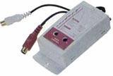
2- The best way to safely do all this is to install between your sound card a device like the one shown in the picture This device is commonly available in any car stereo shop for 2-5 euro and features: a network of resistors to scale down and adjust any audio signal coming from an amplifier, then transformer isolated transfer to your pc card via capacitor also. This will result a feed to your sound card of a scaled down audio signal with a differential ground .IE since ground is big theory its very useful not to have ground of your amplifier signal out and ground of your PC connected in any possible way. A technique like that will provide full safety at all times and a basic reading that may be not accurate but will provide you with an indication if something goes wrong.
3- Links to basic PC scopes http://www.eastelectronics.gr/image/gallery/scope30.zip
www.eastelectronics.gr
part 2
9- By the same technique (as mentioned above you will be able to notice how well is your outputs matched {especially if more than 2 per channel} by monitoring the voltage drop on every resistor .If voltage drop is equal to all resistors with in a margin of 10% then your outs are very well matched .If voltage drop in one is 10mv and the other 50mv then your outs are very badly selected.
10- Please notice that all this procedure takes place with no signal input and absolutely no load to the amplifier. After reached the desired idle that has to be stable also IE no variation , no ups and downs , no multiply then you may allow another 15 minutes for warming up and repeat the all procedure with your amplifier at normal operating temperature and normal operating voltage, starting from offset adjustment.
11- Still you are with no load and no input .There comes the signal generator and the scope .Connect a signal generator set at 1KHZ to the input of the amplifier (if integrated amplifier the features a preamp also it would be wise somehow to separate amplifier boards from preamplifier and apply the signal there .This will result a more accurate reading cause if there is any distortion coming from the preamp stage then this is simply going to be amplified and you may believe that your amp is faulty .
12- Apply some signal (sine wave) and observe your scope .You expect to see the exact signal you apply in the input only more amplified. If you see half the wave form or your wave form is distorted in any way then you have trouble .RECHECK EVERYTHING.
13- With all the safety measures still on you may set the gain of your generator to zero and connect a load on your amplifier .You may connect a resistor of 220-470R 5-10W which is way out of your amplifier limits and spec but is a very easy way to make the amplifier operate without using its full ability .with this load you apply signal from your generator and observe for any changes in the wave form. Feeding your amp with such a load will make your amp operate but the current draw from the all circuit is very low .Also if your amp features a dc protection device and may be your amp has something else wrong but except dc (oscillation for example)then with this load the protection unit may be not activated (also because it is not designed to observe oscillation ) so you may be able to see performance and distortion figures before driving your amp to full load and troubles related to this .
14- If after that all is ok then you remove the load and all the safety measures, put everything as is supposed to be and Recheck (after warming up) offset and idle settings.
Use of PC scope to troubleshoot your amp
1- The use of a pc based scope is NOT RECOMMENDED!!! But if you haven’t anything else available there are a few things that can be done to give you some readings about your amplifier at least as an indication .Pc based scopes together with signal generators are commonly available in the web but some additional safety measures are to be taken since PC scopes work thru your sound card and the safety and performance of this card is limited and your PC may be seriously damaged. Plus that if something is wrong with your amp it’s very likely to send in your sound card a very good amount of dc voltage that cannot handle.
2- The best way to safely do all this is to install between your sound card a device like the one shown in the picture This device is commonly available in any car stereo shop for 2-5 euro and features: a network of resistors to scale down and adjust any audio signal coming from an amplifier, then transformer isolated transfer to your pc card via capacitor also. This will result a feed to your sound card of a scaled down audio signal with a differential ground .IE since ground is big theory its very useful not to have ground of your amplifier signal out and ground of your PC connected in any possible way. A technique like that will provide full safety at all times and a basic reading that may be not accurate but will provide you with an indication if something goes wrong.
3- Links to basic PC scopes http://www.eastelectronics.gr/image/gallery/scope30.zip
www.eastelectronics.gr
Attachments

There might be a slight problem with point #6. Increasing the power supply filter capacitance will increase the surge current during power-on and may damage the rectifier and sometimes the power transformer too as it cannot increased secondary surge currents. So becareful with it
Thanks,
Routhun
Thanks,
Routhun
your remark is very correct
i think your remark is very correct but only if you go from 4.700 mfd to 32.000 mfd ..... if you upgrade two caps that used to be 4700 each and you made them 10.000 then all is going to remain just fine ... its a good point though
thanks
routhun said:There might be a slight problem with point #6. Increasing the power supply filter capacitance will increase the surge current during power-on and may damage the rectifier and sometimes the power transformer too as it cannot increased secondary surge currents. So becareful with it
Thanks,
Routhun
i think your remark is very correct but only if you go from 4.700 mfd to 32.000 mfd ..... if you upgrade two caps that used to be 4700 each and you made them 10.000 then all is going to remain just fine ... its a good point though
thanks
he he he(Carlos)
i have an amp here that was originally 4700ufx2 on the pwr with 2 output transistors per channel(x2)
right now after changing the driver stages to transistors that perform at 1.5A(before it was 1A) ,it has 4 transistors per channel(2sc5200 2sa1943) and 22x4700uf the transformer it's 500va 40 0 40 and it works fine(not to audio sonics extremes)just more power to drive tight and clean bass to 15" black widow(peavey) speakers,.....originnaly the fuse was 4A at 120volt and it's actually the same fuse right now,i play bass guitar on it and it's just fine...for sure the 22 capacitors are a waste but.....they're cheap(63v 4700uf nichikon 3bucks each),so.....
fans,bigger heat sink,
it match

well ....
nico ....nice to hear from u
hope you are doing well ( i dont see any reason why not since line UP is older than you ha ha ha ha ha )
yes .... not really the 70's but just a litle bit younger at that particular time comercial amps had made a lot of improovements plus they kept sonics of the 70's so yes !!!! i like them very much
then again since most of my costumers go for a complete rebuilt meaning electros are gone , resistors replaced, ltp matched , speakers AB switch is gone, supplies upgrated , secondaries too ,multiturns here and there and so on and on then after all that you have a very respectable device in your hand ....
the best thing though is to see it come back to life !!!!
happy regards sakis
hey sakis
i've been reading around here,a bit of everything...and it's getting much more complex h h
can you help me here?
1991 amp,no pre,i drive it with audio interface pc based,heavy work in all these years,.....it's not really a vintage but....
Is it possible to recap with capacitors other then electrolitics,all of them(maybe not all on the power supply)...let's not think on cost or boutique's,only usefull and quality...???????????
i can give more details if this is ever good sense in your opinion...
i really like this amp,it's not a top notch amp,most probably it's ab,i dont know,i think i even have the shematics,not sure...but latelly is getting desapointing,and i'm noticing it changing in a short period of time,it got worst in the last 2 months,and based on what i have been reading i really think it's time for caps and so why not better then elect....
what say your experience?
thank you
Marco
if i understand well
you would like to replace all caps in one amplifier in a patern tha NO electrolytic exist inside .....( except ofcourse power banks )
i have just a few things to tell you
from default there is circuits that work like that : have no electrolytics in the signal or feedback path ...you might consider using a thing like that
doing a replace like that might be not possible since there will be a size issue ( mkt caps will have huge size compaired to electro's)
then again huge componets like that might also work as antenas and then the same design might not work well after changes like that ( may other layout required )
finally ....
place a schematic of your amplifier
in general a few other tweeks can be applyied to make your amp a lot better and still use elctro's
----- bypass with good quality film caps
-----change resistors to metal film
----- play with VAS miller cap
-----play with input filter
----- upgrade caps to a better quality
----- shift idle
----- play with zobel
----- rewire critical things
----- shift safety margins to next level
all the above will make a very nice amp without repalcing the electro's
great sakis(i feel like i'm learning something here)
will it be fine to post the scheme here?????give me some time to do that....
i rewired some parts(eliminate a/b switching and phones output as they are resistors for that not a dedicated amp and the switch in that plug wasn't very trusty),i think almost all resistors r metal film,but the quality of the caps i'm not sure,and besides with all the hours on it......in my opinion it's a very simple amp,not many components per channel....
this is one of the things i would like to do and next i would like to clone this amp but with mods...let's see if time allow's it...
thank u for ur precious time Sakis
Marco
YouTube
Wow! Great videos and photography on your YouTube site!
heheheh.
Carlos
Wow! Great videos and photography on your YouTube site!
Very interesting.
Here's what I've done -- remove the entire driver section, pcb and all and sell it on EBay -- substitute with LM4702, LME49811 etc. I've just been tickled at what the driver board for a 1970's vintage Pioneer receiver will fetch. 1970's vintage receivers are my favorite -- there's plenty of room, enormous heat sinks, good power transformers, AM and FM tuner sections at the peak of their performance etc., etc.
Here's what I've done -- remove the entire driver section, pcb and all and sell it on EBay -- substitute with LM4702, LME49811 etc. I've just been tickled at what the driver board for a 1970's vintage Pioneer receiver will fetch. 1970's vintage receivers are my favorite -- there's plenty of room, enormous heat sinks, good power transformers, AM and FM tuner sections at the peak of their performance etc., etc.
often the approach of restoring is bring a machine to life and if possible to original condition ....
answer to your question will be that yes there is always going to be a margin for playing arround with bias , drivers and outputs , but as a rule i would say that everything is possible but for sure will have an effect at the safety margin of your amplifier ...
so changes are to be made with caution and doyble veryfied with instruments
generally
-total recaping ,
- proper tuning (idle offset) multiturns here and there
-total removal of ceramics and re with s mica or styroflex or multileyer
- mechnaincal ( paste and cooling )
-thermal joints in the ltp
-film resistors where needed
-relocation of zobel
- bit of rewiring
- and a bit of caution in input caps and VAS miller cap
and a bit of here and there will alter the performance dramatically of the amplifier without effecting safety
beyond that all mods are possible but will require another approach
regards sakis
- Status
- This old topic is closed. If you want to reopen this topic, contact a moderator using the "Report Post" button.
- Home
- Amplifiers
- Solid State
- vintage amplifier repair/upgrade manual