Hi there, I have recently resurrected an ETI 5000 power amp which I made what must have been more than 20 years ago. I am not an expert at electronics, but have done some study in the field yonks ago. I see other threads relating to this amp which suggest it is pretty useless. I must have been deaf at the time as I can't recall it sounding that bad. My speakers weren't that good; perhaps that's why.
At any rate, turned it on with no load and first thing it did was blow one of the fuses to the preamp (which I was using). Changed that and tested voltages and so on and it seemed okay. The left channel driver transistor heatsink was a little hotter than the right. Tried it with a load and the first thing it did was trip the speaker protection and give a puff of smoke - left channel only. Turns out it cooked R7 R18 (270R) as well as both BF 469. I changed all the electrolytics, semiconductors except for the mosfets, as well as the cooked resistors.
However, quiescent current is high even using the adjustment, and the driver heatsink does get hot with no load. There are no shorts in the mosfets but I think there may be leakage or whatever going on...does anybody have any ideas regarding this? I guess the next step would be to change the mosfets; I have found some online for about $10. Having said this, i'd only do this for sentimental reasons...i think I will buy another kit when I have the money...I am sure that something else will go bang sooner rather than later.
thanks.
Hi Jonnoh, I am from Adelaide also, and own a pair of these amplifiers which are still in daily use. They have suffered exactly the same fate as yours, only worse. Parts of the board had been reduced to carbon, which presented quite a challenge to rescue.
Maybe your faulty amplifier is oscillating. Is R29 (output Zobel) getting hot? I would be inclined to change all the electrolytic capacitors on the 477 boards. I have implemented a modification suggested by a guy in Sydney called Alex Kethel who is a member of this forum. I also did a modification to the positioning of the feedback pick off point.
PS I was going to send you an email, but notice this is not enabled. Feel free to email me, as being a retired electronic fault fixer I can probably help you.
Keith
Hi Keith, thanks for that.
I don't believe it is oscillating. Output voltage on that channel is around 120mV; on the other (good) channel it is about what they say it should be, around 25mV. I hope this is consistent with not oscillating. Unless it oscillated as soon as I connected the load?
It seemed to be R7 and R18 which were the most badly burnt. R29 and 30 are okay.
I have changed all the electrolytics (except the power supply), as the one thing I managed to remember was that these can become faulty with age. Rail voltages were okay. I don't think there is much more left for me to change except for the mosfets.
If you can offer any advice it would be appreciated. If you can supply info regarding the mods I'd be very interested also...give me something to fiddle with. That's if it ever gets working again.
thanks again.
I have implemented a modification suggested by a guy in Sydney called Alex Kethel who is a member of this forum. I also did a modification to the positioning of the feedback pick off point.
Hi Keith, old thread I know, but stumbled across it as I too am resurrecting my old series 5000.
I am interested to know what these modifications are that you speak of.
Dave
Hi Dave, I also just stumbled across your post.
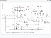
My 477 modules have been out of service for quite a few years and I am trying to recall what I did to them. I think Alex Kethel goes by the forum name sandyk on this forum. He suggested adding an 18 volt Zener diode in series with one of the BF470 transistors to reduce the collector dissipation. He told me he had discussed it with the designer who was in agreement with the idea.
I have also been in email contact with janusz who has a thread on this same amplifier. I think he is from Western Australia, and seems more interested in component upgrades rather than basic reliability issues.
The board design of the 477 modules seems to be in contravention of a practice that Douglas Self has written about. The feedback resistor R19 needs to be connected to the output trace further downstream than the board design intended it to be.
I could probably find my modules and tell you where the Zener diode goes in the absence of documentation.
Keith
Interesting, if historical thread.
I used to use these, and he AEM6500 amplifier which was identical. I suspect that if I dig in my cupboard I will find some PCBs in the back of it somewhere.
To describe these amplifiers as "useless" is foolish - the performance was pretty good even for today, with distortion in the 0.0X% region and lower. Once working these were stable and well behaved. They did use FETS which some people seem overly perturbed by.
The heatsinks on the drivers did run very hot indeed. I added extra aluminium to mine to keep temperatures to a reasonable level.
There was a mod to the output devices, adding a small ceramic cap. If you don't have this in your mod I can go looking for the old articles.
The zener goes between the collectors of Q7 and Q8, making the balance better between sides of the second stage diffamp.
Alternatively insert another 200Ω trimmer and adjust it so it so the two sides are equal.
Thanks for the suggestion Suzy.
Any chance you could elaborate on the details ? What needs to be equal ?
I am only a humble hobbyist with a good soldering iron.
A rough sketch of that part of the circuit would be all I need !
Thanks heaps
David
I was reading from a very blurry schematic. I meant Q7 & Q5. The zener ensures the dissipation in the Q5/Q7 pair is equal to that in the Q6/Q8 pair. A resistor would do similar. Adjust so the voltage across it is the same as that across the bias adjustment pot for equal dissipation.
Attachments
Interesting, if historical thread.
The heatsinks on the drivers did run very hot indeed. I added extra aluminium to mine to keep temperatures to a reasonable level.
There was a mod to the output devices, adding a small ceramic cap. If you don't have this in your mod I can go looking for the old articles.
Yes please googlyone, I would be very very appreciative of the actual specific detail of these mods ( zener, trim pot, ceramic cap, anything else... )
I am not electronics trained and so need it very clearly ( drawn ) explained.
Thanks heaps
David
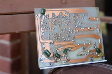
David, The image is of one of my boards. The one that did not get burned up.
The added Zener and cut track are visible. What may not be too obvious is an extended pig tail on the feedback resistor going to one end of the inductor.
Keith
Thanks Keith, your photo of the zener very clearly shows how it is connected.
The feedback resistor is a bit harder to make out but looks to me that it is now connected to the same point as the inductor ?
and PCB .....")
Regards,
Alex
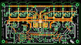
That is a really interesting looking board and layout.
Are they available ?
Is there a parts list ?
You may try this configuration. KSA1142/ksc2682 and ksa992 in VAS simulate better. I use 2sa1209 and 2sc2911 in VAS and no anti-clipping diode in my old eti477. The new one I'm working on has 3 Exicon output pairs.
cheers,
Are the 1209's and 2911's direct replacements for the BF's ?
Any other changes required ?
Are the 1209's and 2911's direct replacements for the BF's ?
Any other changes required ?
They are upgrades in almost any area. VAS in eti477 takes enough current to make transistors without correcting diode/resistor very hot, with diode they are just warm. Nevertheless Sanyos are just better.
cheers,
- Status
- This old topic is closed. If you want to reopen this topic, contact a moderator using the "Report Post" button.
- Home
- Amplifiers
- Solid State
- ETI 477 resurrected but with problems.