in my Chinese PCB, because of this I speak, there are 4 ceramics, that's why I SUGGEST to eliminate them, then one does as he prefers.
The supercap is used to cancel the offset which, otherwise it is difficult to control, but the supercap is a sonic disaster, that's why I RECOMMEND to try the bypasses.
Then if one replaces the 4 5551 and 5401 inputs with the chip containing PNE and NPN, the offset is controlled fine.
Are you using the dual-chip? I'm going to (NPN/PNP), following your suggestion, but:
its maximum power=200mW;
its maximum collector current=200mA;
while the discrete transistors show 600mW and 600mA.
The configuration seems to remain plenty within dual-chip specs, even @±70V I'm using, but I would be glad to you if you will confirm the absence of any problem.
I do not believe.
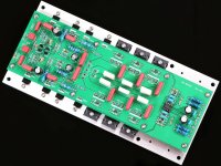
I see 3 pairs of power amplifiers when the original 108 only has 1 pair.
I see the servo circuit in the single pcb while it exists only in the Chinese kits and in separate PCB.
Also there are the resistance on the emitters
Furthermore, the 3 pairs are, theoretically, incorrect:
usually 1 pair, then 2 pairs, then 4 pairs, then 16 pairs etc.
Domenico, this is an analogue design, not a digital oneWhy the need of the powers of two?
true, but if you want to replicate the 108 or improve it / try to improve it I would start from the clone / replica card with 1 pair.
If you like it you keep it that way, otherwise you start working around it, but in the details, not distorting it.
IN MY OPINION .
On the other hand, the proposal to reduce the distortion of the second stage is interesting, but it remains a circuit with obvious limits and, I would say, questionable technical decisions.
that 3 pairs is no longer 108, but a badly cooked mess
If you like it you keep it that way, otherwise you start working around it, but in the details, not distorting it.
Too bad Mr Deletraz was not aware of these limitations before embarking upon the Model2 with its two output pairs and Vbe multiplier. At least he had the sense of not going for 3 pairs
ok.
I do not know what could or could turn in the brain of Mr. Delatraz, I just say that if you like the 108, you can replicate it as you see it and, afterwards, proceed step by step as I did.
Then you can go further, again as I / we did, another input voltage generator, 4 pairs, polarization changes. stabilized power supply etc etc.
but in the face of such work, then, I go in the other direction with another scheme where I can use LT3092 and have an objective increase in performance.
Ah, I forgot that the 2 signal ground resistors, the ones with the supercap, to understand, if I replace them with films and foils I have interesting results.
@analog_sa
mah,
when I see
- similar extra Dartzeel variations
- the zener as a stabilizer of the entrance
- the Wima in series entry
- the ceramics as in my PCB, identical to the original, I am increasingly convinced that the 108 is a summary of a few but confused ideas.
But will it really like it?
mah,
when I see
- similar extra Dartzeel variations
- the zener as a stabilizer of the entrance
- the Wima in series entry
- the ceramics as in my PCB, identical to the original, I am increasingly convinced that the 108 is a summary of a few but confused ideas.
But will it really like it?
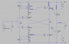
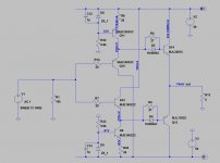
And here is Damir's circuit as a possible replacement for the diamond.
And it works in real life without thermal runaway? I doubt that.
And it works in real life without thermal runaway?
That is a pretty good question. You reckon having all the transistors sharing the same sink won't be enough? Because of the darlington?
That is a pretty good question. You reckon having all the transistors sharing the same sink won't be enough? Because of the darlington?
Output bjts without degeneration even with vbe multiplier for thermal tracking are very tricky task. Maybe with higher value of base stoppers like in the original circuit...
It sould be tried in real life with lot of experimentation.
The original dartsil is full of mysteries, what do we see? Capacitors Wima MKS, ceramics AVX CK (in Chinese clones, judging by the information, silver mica Philips), resistors are not the steepest MRS25, and I think the transistors are not very good, and they just put a supercapacitor. But judging by the reviews, it plays (original), and even as. And what was impossible at such a price to cram normal parts?
And here is Damir's circuit as a possible replacement for the diamond.
I knew the original idea, base of Damir's topology, that I didn't know by itself. I'm not sufficiently skilled to place a comment on the modded diamond. For sure the collectors of front-end transistors, now, bring a portion of the signal that injects in the emitters of (originally) back-end transistors (here middle transistors), resulting in a subtraction, being in phase. I do not know if this is a good or bad thing but, perhaps, some of you do, please, share!
The main improvement by Damir, IMHO, resides in adopting one more stage between the diamond and the load, then the diamond's behavior improves for two reasons:
- the diamond is 1/hfe(last pair) influenced by the load with respect to the original condition;
- the output impedance in no more dependent from the CCSs (upon their limit - that is more than plenty in full driving capability for any load in this world) and you can use as many pairs as you want in order to lower it.
The VAS's behavior too improves of the same 1/hfe factor projected back by the diamond.
Last edited:
The VAS's behavior too improves of the same 1/hfe factor projected back by the diamond.
Not really in the context of the 108, where the VAS is a discrete, high bias opamp. Loading is a very minor effect.
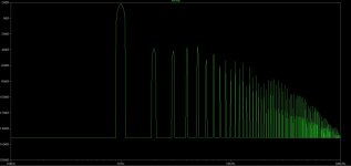
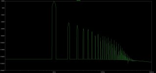
Here is the simulated distortion of the output stages alone. Both at 20W, 4ohms. Damir's has more than 3 times lower thd and the spectral distribution looks much healthier. Same bias current through the outputs.
Attachments
A lot better!
The two "patented" diodes placed to the bases of the second stage, paralleled to the Rs, do switch. So we expect some distortion from them. Try the simulation removing diodes and remaining at a power so low that the voltage on the Rs will be lower than diode's threshold. Then lower the Rs and try again to find the best distortion with the highest Pout. Forget about the idle bias, it is a simulation.
My NSCB has switching diodes too but their distortion should be a lot lower than the distortion from a switching transistor.
Last edited:
- Home
- Amplifiers
- Solid State
- Dartzeel amp schematic - build this?