Not possible for the lack of any serious capacitance after the bridge.
There are a couple of electrolytes of, maybe 1000uF, next to it. Why would they use such a big rectifier bridge, then? IF it is a BU6-04F it is rated at 6A.
Last edited:
There is another pair of similar sized electrolytic capacitors close to the ones next to the rectifier bridge.
What voltage would a driver stage have? I do not know, just trying to figure out what is populating that MB.
Why do they use a 6A rectifier bridge there? What do you think?
What voltage would a driver stage have? I do not know, just trying to figure out what is populating that MB.
Why do they use a 6A rectifier bridge there? What do you think?
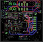
Hi. That could be my take on the NHB-108 pcb under the power transformer.
I used the already excellent Mark Johnson Power-On Softstart PCB design that I modified and Added the transfo surronding parts, including the 4 secondaries Parallel/Serie switch. It also include a high current rectifier that will be bolted on the amp bottom plate. The circuit includes:
-Mark's power-on and softstart with 5V SMPS standby power supply, this module support 85-305Vac so no need for the line voltage selection.
-The original Shurter 115/230V volt selector is monted on the corner of the transfo plate, and wires connect to the transfo primaries, replacing Mark's P8-P10 jumpers.
-The Shurter original fuse socket is in line with the main power before entering the Power-On section.
-Added pads for the Crowbar protection (to use or not) to connect the SCR directly on the Caps+ and Caps- to discharge the power supply in case of a fault. The SCR is directly wires to the protection pcb...
-Added Stackon connector option in addition to the 6.35mm pitch Phoenix ac connectors. We can also solder the transfo wires directly to large pads.
-Added AC input film capacitors option. Can be installed on just one pcb since the AC input is shared by both pcb...
-Added the hi-current rectifier with snubbers, taking its AC input directly from the transfo secondaries. It can be bolted directly on the amp bottom. The filtering caps can them be wired with hi-current wires directly conencted on the rectifier large screws...
-Added the 4 secondaries (using two dual 18V smaller transfo, with common primaries, making a possible 'clone of the actual custom Dartzeel transfo). A simple toggle 4PDT switch (rated at 6.0A) to select Parallel or Series connection.
-Added the inner fixed secondaries output AC (18-0-18Vac) to supply the futur protection PCB (as the original does)
-Added an Overtemp protection sensor (NC if temp < overtemp point). The input cut the <PWR_ON> signal on the circuit, killing the Triac and bypass relay, turning the amp off...
-In this version I kept the dual leds power-on, power-off, but they can be removed since they won't be use on the amp. Further mods such as the momentary jumper and softstart selection options could be removed, by selecting the correct softart and switch option.
-An other step could be to replace most of the logic with SMD parts to reduce the control section PCB footprint
But you get the idea...
Attachments
Last edited:
What voltage would a driver stage have?
For a follower type output stage it should be higher than the output stage. Or the same, but certainly not less. So, let's say 2200uf/120v as a minimum. Have you seen what a cap like that looks like?
Ok, I may use the wrong terminolgy.
If a driver transistor can use 120V then there is no problem, that voltage is readily available in bundles from the 1000VA transformer and 10x15.000 uF power supply.
If the input stage, maybe in the form of an IC that requires +-12-18VDC Dartzeel could use some smaller rectifier bridge and voltage regulators/electrolytic capacitors.
But there is a rather big rectifier, maybe 6A and I thought there may be a need for intermediate voltages also, say 40-50VDC? I just assumed an intermediate (I assumed they are called Driver Stage - to drive the Power transistors?) stage needed an intermediate voltage")
You tell me
I have never Designed an amplifier.
Still wondering what that Big rectifier bridge is doing at that location on the MB..
If a driver transistor can use 120V then there is no problem, that voltage is readily available in bundles from the 1000VA transformer and 10x15.000 uF power supply.
If the input stage, maybe in the form of an IC that requires +-12-18VDC Dartzeel could use some smaller rectifier bridge and voltage regulators/electrolytic capacitors.
But there is a rather big rectifier, maybe 6A and I thought there may be a need for intermediate voltages also, say 40-50VDC? I just assumed an intermediate (I assumed they are called Driver Stage - to drive the Power transistors?) stage needed an intermediate voltage
You tell me
I have never Designed an amplifier.
Still wondering what that Big rectifier bridge is doing at that location on the MB..
Last edited:
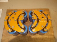

Capacitor Bank Brackets are working fine...
I get nervous when I see these arrangements. If you drop a screwdriver or your watch shorts these, its like an arc welder in your amp. Also whats the current thinking on these big caps. Do computer grade caps offer sonic advantages over snap-in caps? Sorry I don't want to get into another debate on caps a yes or know will suffice
your watch shorts these, its like an arc welder in your amp.
Seriously? The original copper arrangement is a lot more dangerous, yet it is being manufactured in the watch capital of the world
Comparing caps with screw terminations vs snap ins is not easy as those seem always different in more ways than just termination.
Per example, a direct comparison between Mlytic snap in and screw types with identical capacitance but different voltage ratings makes me prefer the snap ins.
I would think the best approach is to have one big cap near each output transistor.
No argument there, but it requires a different construction, more like a Spectral.
I get nervous when I see these arrangements. If you drop a screwdriver or your watch shorts these, its like an arc welder in your amp. Also whats the current thinking on these big caps. Do computer grade caps offer sonic advantages over snap-in caps? Sorry I don't want to get into another debate on caps a yes or know will suffice
This is nothing I use 600.000 uf in some amps.
Erlend, be careful with your Swiss watch
If I had a watch.
My Dartzeel will only have 80.000 uf for each channel.
600.000 uf for my Aleph 5.
Erlend, be careful with your Swiss watch
It is not so much a watch as it is a bracelet issue. Especially if it is made out of stainless steel and there is a temperature sensitive wrist clasped inside
Hello to all . The original uses resistors MPS 25 which is 6.5 mm long, power 0.6 watts, I want to use TAKMAN resistors, but they have 9 mm long, power 0.5 watts, they do not fit in. The question is whether it is possible to use these resistors (and other better ) power of 0.25 watts, their length is also 6.5 mm?:смущенный:
- Home
- Amplifiers
- Solid State
- Dartzeel amp schematic - build this?