I guess I'm still a kid who likes stickers ") It's also easy to re-use the case for another build, and just slap another sticker on it. At the moment I'm happy with the sound. It's now connected to the tweeters in my main system and it's time for some listening.
It's also easy to re-use the case for another build, and just slap another sticker on it. At the moment I'm happy with the sound. It's now connected to the tweeters in my main system and it's time for some listening.
Fuse is integrated in the IEC socket on the back. I debated with myself about putting fuses on the rails too, but I worry a bit about PS impedance on amps, and I did not find anything suitable in my boxes, so only one main fuse it was
It's also easy to re-use the case for another build, and just slap another sticker on it. At the moment I'm happy with the sound. It's now connected to the tweeters in my main system and it's time for some listening.Fuse is integrated in the IEC socket on the back. I debated with myself about putting fuses on the rails too, but I worry a bit about PS impedance on amps, and I did not find anything suitable in my boxes, so only one main fuse it was
Back again.. things have 'escalated' and I decided to build another amp with dart clones + a pair of LJM MX50SE for bass duty.
The reasoning is that for normal passive speakers, this one can be used for bi-amping, letting each amp do what it does best. In my active 3-way setup at home, I use it for bass and mids, and the first dart I built is taking care of treble.
The first one I built was with 30V rails, and this one is with 40V with a little twist. I used two toroids with single secondary (80VDC), so the midpoint is floating. This compensates for the varying DC-offset and possibly acts as some kind of DC protection too. It was a bit scary to connect it up with actual speakers at first, but it seems to work pretty well. I had to add a high value resistor from negative rail to the floating ground on the MX50 to make the current draw symmetrical, or it would pull those ~2,5mA through the speaker load.
With just the dart clones running with the floating ground, there is a damped LF oscillation at around maybe 1Hz that can be seen at switch on, or if the source creates a DC step in the signal, the woofer slowly moves in and out a few times. I had the same behavior in a JLH-69 with floating ground too, but it was not an issue in daily use. However, with the MX50 boards and loads connected, this is stable, and there is no sign of LF oscillation. PS is CRC type, no cap multiplier this time around.
I have done some subjective and objective testing with lower value base resistors on the outputs, but even if measurements indicate lower values being better, I still prefer the standard values for mid & treble. Bass definitely improves with the lower resistor values, but in my case that is not relevant, I only aim for 'pleasant' mids and treble. I feel the with and depth of the soundstage decreases with resistance. Since this a 'subjective only' amp, I just ignore the measurements, and go with what I like to hear
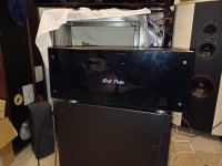
Here are a few pics of the latest build:


Toroids are in the green 'box' and there is a on/off switch under there too.
I still have an idea to replace the front with Lexan, putting black vinyl on the back side with text cut into the vinyl, and a display backlight behind the cut out text.
The reasoning is that for normal passive speakers, this one can be used for bi-amping, letting each amp do what it does best. In my active 3-way setup at home, I use it for bass and mids, and the first dart I built is taking care of treble.
The first one I built was with 30V rails, and this one is with 40V with a little twist. I used two toroids with single secondary (80VDC), so the midpoint is floating. This compensates for the varying DC-offset and possibly acts as some kind of DC protection too. It was a bit scary to connect it up with actual speakers at first, but it seems to work pretty well. I had to add a high value resistor from negative rail to the floating ground on the MX50 to make the current draw symmetrical, or it would pull those ~2,5mA through the speaker load.
With just the dart clones running with the floating ground, there is a damped LF oscillation at around maybe 1Hz that can be seen at switch on, or if the source creates a DC step in the signal, the woofer slowly moves in and out a few times. I had the same behavior in a JLH-69 with floating ground too, but it was not an issue in daily use. However, with the MX50 boards and loads connected, this is stable, and there is no sign of LF oscillation. PS is CRC type, no cap multiplier this time around.
I have done some subjective and objective testing with lower value base resistors on the outputs, but even if measurements indicate lower values being better, I still prefer the standard values for mid & treble. Bass definitely improves with the lower resistor values, but in my case that is not relevant, I only aim for 'pleasant' mids and treble. I feel the with and depth of the soundstage decreases with resistance. Since this a 'subjective only' amp, I just ignore the measurements, and go with what I like to hear
Here are a few pics of the latest build:
Toroids are in the green 'box' and there is a on/off switch under there too.
I still have an idea to replace the front with Lexan, putting black vinyl on the back side with text cut into the vinyl, and a display backlight behind the cut out text.
Onsemi semiconductors were restocked and got around to it and reworked all the chi-fi semiconductors to +/- matched originals including the zeners (i used 5w onsemis) and also swapped 15r base resistors and removed the "magic diodes". Finally a matured, nice, sweet, airy and musical sound that does not "harden" at higher levels anymore👌 Very nice!


I think removing the diodes is the best solution. With 15Ohm and the CCS set at 118mA you have a voltage drop of 2.7V across them (with diodes it would be 0.6V), have you tried decreasing the value further below 15Ohm? Some use no base resistors but have the Res of 0.33Ohm to prevent a thermal runaway. One of the best features of this design is that it doesn't use any Re.
Congrats!
I ordered the second pair as a kit too, but the transistors were definitely not original ON components. Easy to spot with them side by side, and the hfe measured outside the specs too.. I did use the other components supplied though, and can't say I can hear or measure any difference.
Did you try it with the standard value base resistors after you replaced the transistors? As I mentioned before, I think they sound better in mids & treble like that. No diodes mounted though. If they need to do bass-duty, the overall compromise might be towards lower base resistor values though, speaker load and taste may vary too. Subjectively I think this amp sounds different, and does a lot of things right.
Last edited:
@marigno 2.7V across base resistors sounds wrong to me.. there are only some very small currents through the base resistors at idle so voltage drop is very low. Only at really high output currents will the voltage drop across the resistor increase enough to cause the diodes to conduct.
I agree on the Re, I think the whole idea of the arrangement of the output stage is to make it reasonably stable without them.
I agree on the Re, I think the whole idea of the arrangement of the output stage is to make it reasonably stable without them.
It was a typo.
Under full driving conditions, the maximum current supplied to the bases is 118mA each, equivalent to a 16A peak on the load if the final pair hFE is 70.
It is easy to calculate by Ohm's law the voltage across those resistors is 1.77V, to subtract from the driving voltage swing.
Under full driving conditions, the maximum current supplied to the bases is 118mA each, equivalent to a 16A peak on the load if the final pair hFE is 70.
It is easy to calculate by Ohm's law the voltage across those resistors is 1.77V, to subtract from the driving voltage swing.
- Home
- Amplifiers
- Solid State
- Dartzeel amp schematic - build this?