3 pairs of stereo 
beauty.........[USD 728.93] DIY reprint Black Widow NHB-458 full balance BTL post stage power amplifier - Wholesale from China online shopping | Buy asian products online from the best shoping agent - ChinaHao.com
I think the 108 clones, not the real NHB-458.
beauty.........[USD 728.93] DIY reprint Black Widow NHB-458 full balance BTL post stage power amplifier - Wholesale from China online shopping | Buy asian products online from the best shoping agent - ChinaHao.com
I think the 108 clones, not the real NHB-458.
Attachments
3 pairs of stereo
beauty.........[USD 728.93] DIY reprint Black Widow NHB-458 full balance BTL post stage power amplifier - Wholesale from China online shopping | Buy asian products online from the best shoping agent - ChinaHao.com
I think the 108 clones, not the real NHB-458.
beauty.........[USD 728.93] DIY reprint Black Widow NHB-458 full balance BTL post stage power amplifier - Wholesale from China online shopping | Buy asian products online from the best shoping agent - ChinaHao.com
I think the 108 clones, not the real NHB-458.
I think the 108 clones, not the real NHB-458.
Most certainly it is not. A silly servo, sound-degrading output relays...it is just a misuse of the 108 circuit. Besides, the 458 does not use the array of To220s but just 3 per channel.
Last edited:
Most certainly it is not. A silly servo, sound-degrading output relays...it is just a misuse of the 108 circuit. Besides, the 458 does not use the array of To220s but just 3 per channel.
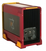
Someone re-engineered the 458 and he came up with this.
At first, he just wanted to test it but he got a very positive result so he made a decent enclosure for it and he uses it as his main amp next to a very high-quality DIY hybrid amp.
Second picture the original 458 (not DIY)
Attachments
I know. It's old news. Looking at the factory movie his circuit is probably accurate, but until someone disassembles his amp there is no way to be 100% certain. As the 108mk2 is supposed to follow the same topology with a single o/p pair and readjusted op points for the lower supply voltage i have been meaning to try it out in place of my 108 clone. Very interesting that it is bye - bye diamond. Perhaps the circuit is now even more stable and certainly having a different distortion spectrum. Owners who have upgraded all tend to be ecstatic, but of course this is meaningless. I have some misgivings about the huge caps decoupling the nfb, but to be fair, for an expensive production amp it is highly irresponsible to rely on the end user adjusting constantly the offset.
A four pair amp looks great as an idea, but where can we find the pcb's? I've done a search on ebay and haven't found anything.
the pcb does not exist.
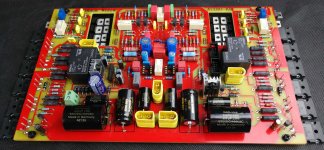
I bought the Chinese pcb with the single pair and I reviewed the scheme
added 3 pairs, changed the polarizations, some capacitors, changed MJE drivers
at the 4 pairs an emitter resistance of 0.22 ohm 5 watts has been placed and everything is wired wired , with an aluminum bar that fixes the 4 couples to the heatsink
changed the entry capacitor and put a cap of 22 millifarad, bypassed, to ground between R 9 and 10
VCC of 60 VDC drivers, 50 VDC finals
Last edited:
Someone re-engineered the 458 and he came up with this.
At first, he just wanted to test it but he got a very positive result so he made a decent enclosure for it and he uses it as his main amp next to a very high-quality DIY hybrid amp.
Second picture the original 458 (not DIY)
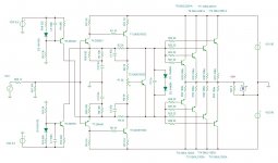
what is that scheme?
I hope I don't bother you much but I am trying to figure out some things. As I've mentioned on my earlier posts, my amplifier does take some inteference from surrounding devices, but it seems that it also has a grounding problem. I've opened it yesterday and found out the following:
a) The mains ground is connected to the chassis ( I will further call it "ground spot" ),
b) the rectification boards do not provide the ground directly to the ground spot, but they are grounded via the screws.
c) The speaker outputs are not directly connected to the grounding spot but there is continuity when measured with an ohm meter.
d) the input connectors are not grounded at all. they are directly connected to the amplifier board and have no connection to the grounding spot. I suppose that in this way the input ground is shared wy the preamplifier's ground via the interconnects because once I've accidentaly operated the power amplifier without interconnect attached, I've heard a loud noise on my speakers.
I have a centerboard of a bryston 3B power amplifier and see that all the above are connected to the mains ground via a star-like ground plane but I would like your opinion since you are much aware of this particular amplifier.
I've also measured the dc offset on my power amplifier's output ( although with speakers connected for the time being since I am not sure what will happen if I operate this amplifier without load and haven't bought dummy load resistors yet) and measured 0mv on my right channel and 30mv on my left channel ( that the sound is heard ). I've swapped the speaker cables and the noise is still being heard from the speaker that is connected to my amplifier's left output ( so, it's heard from the right speaker after the swap ).
Last edited:
Hi Misters,
I would like to built one but don't know witch one... what are your recommendations between these two types selling on aliexpress :cheapest one with black pcb and 2 pairs of MJE15034/MJE15035 or the one green pcb and one pair of MJL1302 / 3281?
I think later to explore I could add two output transistors and supercap for exemple.
Many thanks for your experience.

English only please.
Impedance of my speakers is 5 ohms.
You say counterfeit and bad quality from experience? Is it a generality?
Thank you

I bought the Chinese card, but had several problems
the transistors are not matched and with a scheme this is a problem
so better to think of matcharseli alone and everything will be fine
I have changed the board with 4 pairs of final transistors per channel
changed Z1 and Z 2
changed R 19 and R 20
changed the drivers for Q 8, 10, 90 and 100
eliminated Z 5 and Z 6: powered input stages with 317 power supply in cascade to the driver's stabilized power supply (60 VDC)
changed Q 1, 2, 3 and 4 with BCM53DS
inserted scottky diodes on the VCC driver and input, after the drivers and before Q 1, 2, 3 and 4
powered input stages with 317 power supply
So you don't have a cap in the nfb decoupling?
I would have thought a regulated PS for the front end would make the offset worse.
How much does your offset vary? What are the input and output voltages of your regulator? How does a 317 cope? Do you have a separate transformer?
- Home
- Amplifiers
- Solid State
- Dartzeel amp schematic - build this?